
User manual

CY8C29466, CY8C29566
CY8C29666, CY8C29866
Document Number: 38-12013 Rev. *M Page 7 of 47
7. Designing with PSoC Designer
The development process for the PSoC device differs from that
of a traditional fixed function microprocessor. The configurable
analog and digital hardware blocks give the PSoC architecture a
unique flexibility that pays dividends in managing specification
change during development and by lowering inventory costs.
These configurable resources, called PSoC Blocks, have the
ability to implement a wide variety of user selectable functions.
The PSoC development process can be summarized in the
following four steps:
1. Select Components
2. Configure Components
3. Organize and Connect
4. Generate, Verify, and Debug
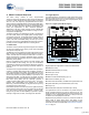
7.1 Select Components
Both the system-level and chip-level views provide a library of
prebuilt, pretested hardware peripheral components. In the
system-level view, these components are called “drivers” and
correspond to inputs (a thermistor, for example), outputs (a
brushless DC fan, for example), communication interfaces
(I
2
C-bus, for example), and the logic to control how they interact
with one another (called valuators).
In the chip-level view, the components are called “user modules”.
User modules make selecting and implementing peripheral
devices simple, and come in analog, digital, and programmable
system-on-chip varieties.
7.2 Configure Components
Each of the components you select establishes the basic register
settings that implement the selected function. They also provide
parameters and properties that allow you to tailor their precise
configuration to your particular application. For example, a Pulse
Width Modulator (PWM) User Module configures one or more
digital PSoC blocks, one for each 8 bits of resolution. The user
module parameters permit you to establish the pulse width and
duty cycle. Configure the parameters and properties to
correspond to your chosen application. Enter values directly or
by selecting values from drop-down menus.
Both the system-level drivers and chip-level user modules are
documented in data sheets that are viewed directly in the PSoC
Designer. These data sheets explain the internal operation of the
component and provide performance specifications. Each data
sheet describes the use of each user module parameter or driver
property, and other information you may need to successfully
implement your design.
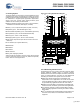
7.3 Organize and Connect
You can build signal chains at the chip level by interconnecting
user modules to each other and the I/O pins, or connect system
level inputs, outputs, and communication interfaces to each
other with valuator functions.
In the system-level view, selecting a potentiometer driver to
control a variable speed fan driver and setting up the valuators
to control the fan speed based on input from the pot selects,
places, routes, and configures a programmable gain amplifier
(PGA) to buffer the input from the potentiometer, an analog to
digital converter (ADC) to convert the potentiometer’s output to
a digital signal, and a PWM to control the fan.
In the chip-level view, perform the selection, configuration, and
routing so that you have complete control over the use of all
on-chip resources.
7.4 Generate, Verify, and Debug
When you are ready to test the hardware configuration or move
on to developing code for the project, perform the “Generate
Application” step. This causes PSoC Designer to generate
source code that automatically configures the device to your
specification and provides the software for the system.
Both system-level and chip-level designs generate software
based on your design. The chip-level design provides application
programming interfaces (APIs) with high level functions to
control and respond to hardware events at run time and interrupt
service routines that you can adapt as needed. The system-level
design also generates a C main() program that completely
controls the chosen application and contains placeholders for
custom code at strategic positions allowing you to further refine
the software without disrupting the generated code.
A complete code development environment allows you to
develop and customize your applications in C, assembly
language, or both.
The last step in the development process takes place inside the
PSoC Designer’s Debugger subsystem. The Debugger
downloads the HEX image to the ICE where it runs at full speed.
Debugger capabilities rival those of systems costing many times
more. In addition to traditional single-step, run-to-breakpoint and
watch-variable features, the Debugger provides a large trace
buffer and allows you define complex breakpoint events that
include monitoring address and data bus values, memory
locations and external signals.
[+] Feedback