CY8CKIT-049-4xxx PSoC® 4 Prototyping Kit Guide Doc. #: 001-90711 Rev. *G Cypress Semiconductor 198 Champion Court San Jose, CA 95134-1709 Phone (USA): +1.800.858.1810 Phone (Intnl): +1.408.943.2600 http://www.cypress.
Copyrights Copyrights © Cypress Semiconductor Corporation, 2014-2015. The information contained herein is subject to change without notice. Cypress Semiconductor Corporation assumes no responsibility for the use of any circuitry other than circuitry embodied in a Cypress product. Nor does it convey or imply any license under patent or other rights.
Contents Safety Information 1. Introduction 1.1 1.2 1.3 1.4 27 Board Details .............................................................................................................27 Theory of Operation...................................................................................................28 Functional Description ...............................................................................................28 4.3.1 Power Supply System ...................................................
Contents 5.4.2 Entering Bootloader Mode from the Bootloadable Application ...................... 51 6. USB-Serial Configuration 6.1 6.2 A. Appendix A.1 A.2 A.3 65 CY8CKIT-049-4xxx Schematics ................................................................................ 65 Programming a CY8CKIT-049-4xxx Project Using MiniProg3 .................................. 72 Bill of Materials ..........................................................................................................
Safety Information Regulatory Compliance The CY8CKIT-049-4xxx Prototyping Kit is intended for use as a development platform for hardware or software in a laboratory environment. The board is an open system design, which does not include a shielded enclosure. This may cause interference to other electrical or electronic devices in close proximity. In a domestic environment, this product may cause radio interference. In such cases, you may be required to take adequate preventive measures.
Safety Information General Safety Instructions ESD Protection ESD can damage boards and associated components. Cypress recommends that you perform procedures only at an ESD workstation. If such a workstation is not available, use appropriate ESD protection by wearing an antistatic wrist strap attached to the chassis ground (any unpainted metal surface) on your board when handling parts. Handling Boards CY8CKIT-049-4xxx boards are sensitive to ESD. Hold the board only by its edges.
1. Introduction Thank you for your interest in the PSoC® 4 CY8CKIT-049-4xxx family of prototyping kits. The prototyping kit is designed as an easy-to-use and inexpensive prototyping platform for users wishing to rapidly develop products using the PSoC 4 families and use the unique flexibility of the PSoC 4 architecture. Designed for flexibility, these kits offer an open footprint breakout board to maximize the end utility of the PSoC 4 device.
Introduction 1.2 Getting Started This user guide helps you to get acquainted with the PSoC 4 Prototyping Kit. The Software Installation chapter on page 13 describes the installation of the PSoC Creator software. The Kit Operation chapter on page 17 explains how to program the kit using a bootloader or a MiniProg3. The Hardware chapter on page 27 details the hardware operation of the kit.
Introduction 1.3.1 PSoC Creator PSoC Creator is a free Windows-based Integrated Design Environment (IDE). It enables concurrent hardware and firmware design of systems based on PSoC 3, PSoC 4, and PSoC 5LP. See Figure 1-2 – with PSoC Creator, you can: 1. Drag and drop Components to build your hardware system design in the main design workspace 2. Codesign your application firmware with the PSoC hardware 3. Configure Components using configuration tools 4. Explore the library of 100+ Components 5.
Introduction 1.3.2 PSoC Creator Code Examples PSoC Creator includes a large number of code example projects. These projects are available from the PSoC Creator Start Page, as Figure 1-3 shows. Example projects can speed up your design process by starting you off with a complete design, instead of a blank page. The example projects also show how PSoC Creator Components can be used for various applications. Code examples and datasheets are included, as Figure 1-4 on page 11 shows.
Introduction Figure 1-4. Code Example Projects, with Sample Code 1.3.3 PSoC Creator Help Visit the PSoC Creator home page to download the latest version of PSoC Creator. Then, launch PSoC Creator and navigate to the following items: ■ Quick Start Guide: Choose Help > Documentation > Quick Start Guide. This guide gives you the basics for developing PSoC Creator projects. ■ Simple Component example projects: Choose File > Open > Example projects.
Introduction 1.3.4 Technical Support If you have any questions, our technical support team is happy to assist you. You can create a support request on the Cypress Technical Support page. If you are in the United States, you can talk to our technical support team by calling our toll-free number: +1-800-541-4736. Select option 2 at the prompt. You can also use the following support resources if you need quick assistance. 1.4 ■ Self-help. ■ Local Sales Office Locations. Document Conventions Table 1-1.
2. 2.1 Software Installation Before You Begin All Cypress software installations require administrator privileges, but these are not required to run the software after it is installed. Close any other Cypress software that is currently running before installing the kit software. Note: The kit contents are installed in the C:\Program Files\Cypress folder by default. If the Code examples are being run from the default install location, administrator privileges are required.
Software Installation Note: Adobe Reader is required to view kit documents. If Adobe Reader is not installed on your PC, the installer provides the link to download and install it. Note: PSoC Creator is provided with a free Keil C licence that has to be registered within 30 days of installing PSoC Creator. To register your Keil license, you will require an internet connection. Please read http://www.cypress.com/?id=4&rID=38519 for more details. Please read http://www.cypress.
Software Installation 2.6 Open the “PSoC 4 Code” Code Example in PSoC Creator Note: The code examples require administrator privileges if they are run directly from the default install location (C:\Program Files\Cypress). If you do not have administrator privileges, copy the Firmware folder from the default install location to any other location on your PC and use the files. 1. Launch the PSoC Creator software from the Start menu. Figure 2-1. PSoC Creator Start Page 2. Open the SCB_Bootloader.
Software Installation 16 CY8CKIT-049-4xxx PSoC® 4 Prototyping Kit Guide, Doc. #: 001-90711 Rev.
3. Kit Operation The PSoC 4 Prototyping Kit is simplistic in design and focuses on providing you with complete access to develop applications using the PSoC 4 device family. The development kit supports a number of onboard functions such as an LED, push button, through-hole connections, USB-Serial connectivity to the PC, and a breakable board design to separate the two target boards. Figure 3-1. PSoC 4 Prototyping Kit 3.
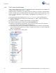
Kit Operation Figure 3-3. PSoC 4 Prototyping Kit Connected to the Computer 3.2 CY8CKIT-049-4xxx USB COM Port When you connect the CY8CKIT-049-4xxx to the PC over a USB interface, it enumerates as a COM port device under the Device Manager window on the Windows OS. Often, the COM port number will be higher than any existing COM port value. For example, in the following image the CY8CKIT-049-4xxx enumerates as COM37. Figure 3-4.
Kit Operation Figure 3-6. Driver Software Installation Complete Note: The baud rate settings do not apply to the virtual COM port as the data transmission is taking place using the Full-Speed USB bus at 12 Mbps. However, because of the virtual COM port driver that sits between the PC and the USB-Serial device, the operating system will see the device as a normal serial port and you will be able to set the baud rate. However, these settings may be ignored. 3.
Kit Operation 2. Open the SCB_Bootloader.cywrk workspace from Examples and Kits > Kits. Select CY8CKIT-049-41xx folder for CY8CKIT-049-41xx PSoC 4 Prototyping Kit and CY8CKIT-049-42xx folder for CY8CKIT-049-42xx PSoC 4 Prototyping Kit. 3. Select the folder where you want to save the project and click OK. Figure 3-7. Open the Project 20 CY8CKIT-049-4xxx PSoC® 4 Prototyping Kit Guide, Doc. #: 001-90711 Rev.
Kit Operation 4. Click on Build > Build All Projects. Note: The UART_Bootloader project is a dependency for the Bootloadable Blinking LED project. Hence, both example projects must be built by selecting Build > Build All Projects. 5. In the Workspace Explorer, right-click the Bootloadable Blinking LED project and select Set As Active Project. Figure 3-8. Set the Code Example as Active Project The bootloadable project must be associated with the bootloader project's HEX and ELF files.
Kit Operation 7. In the schematic view, right-click the Bootloadable component and select Configure. Figure 3-10. Configure the Bootloader Component 22 CY8CKIT-049-4xxx PSoC® 4 Prototyping Kit Guide, Doc. #: 001-90711 Rev.
Kit Operation 8. In the configuration window, select the Dependencies tab and click the Browse button to point to the HEX and ELF files present in the ‘Dependencies’ folder under project directory; click OK. The file paths (assuming the CY8CKIT-040-42xx) will appear as follows: \SCB_Bootloader\UART_Bootloader.cydsn\CortexM0\ ARM_GCC_484\Debug\UART_Bootloader.hex \SCB_Bootloader\UART_Bootloader.cydsn\CortexM0\ ARM_GCC_484\Debug\UART_Bootloader.elf Figure 3-11.
Kit Operation 10.Connect the CY8CKIT-049-4xxx prototyping board to the PC. When connecting the kit to the port, depress the SW1 button as it is plugged in. You will notice that the blue LED begins to blink rapidly; this indicates that the PSoC 4 is in 'Bootloader Mode' and is ready to be loaded with the latest firmware. This must be done each time you bootload the PSoC 4. 11. Select Tools > Bootloader Host to open the Bootloader Host tool. Figure 3-13.
Kit Operation 12.Click Filters and select the Show UART Devices option from the Port Filters window and click OK. This lists all COM devices connected to the computer. Note: The PID of the Bootloader is F13B. You may enter this PID in the Port filters window to list only the Kit Bootloader. Figure 3-15. Port Filters The Bootloader Host tool will now display all of the available UART based COM ports. 13.
Kit Operation 3.4 USB-UART Default Settings The default configuration of the USB-Serial device on the CY8CKIT-049-4xxx prototyping kit is the USB-UART mode. The CY8CKIT-049-4xxx also enables a default UART connection between the USB-Serial device and the PSoC 4. This connection is indicated by two parallel 4-pin headers in the middle of the board. The default pin connections are shown in Table 3-2. Table 3-1. Pin Mapping for USB-Serial Port and PSoC 4 UART USB-Serial UART TX PSoC 4 UART P4.
4. 4.
Hardware 4.2 Theory of Operation PSoC 4 is a new generation of programmable system-on-chip device from Cypress for embedded applications. It combines programmable analog, programmable digital logic, programmable I/O, and a high-performance ARM Cortex-M0 core. With PSoC 4, you can create the combination of peripherals required to meet your application's specifications.
Hardware 4.3.1.1 Measure PSoC 4 Current Consumption You can measure the current consumption of the PSoC 4 device by using one of these methods: Method 1: 1. Separate the USB-Serial board by 'snapping' the perforated edge between the two boards. 2. Power the remaining prototyping board via any of the VDD terminals. 3. Place an ammeter in series with the VDD connection to measure the current consumption. Method 2: 1. Remove the resistor R6 and install a 2-pin jumper in the supplied holes of J4. 2.
Hardware 4.3.3.1 Functionality of the J1 and J2 Headers (PSoC 4) The main PSoC 4 board contains two dual-inline headers (J1 and J2). These headers are both 1×22-pin headers and include all of the I/O available on the PSoC 4 devices. These headers support all of the available ports, GND, VDD, and connections to passive elements and user-input devices. The J1 and J2 headers support 100-mil spacing, so you can solder the male connectors to connect the CY8CKIT-049-4xxx to any development breadboard.
Hardware Table 4-2. J2 Header Pin Details PSoC 4 GPIO Header (J2) Pin 4.3.3.2 Signal Description J2_01 VDD Power J2_02 GND Ground J2_03 RESET Reset J2_04 P3.3 GPIO/SWDCLK J2_05 P3.2 GPIO/SWDIO J2_06 P3.7 GPIO J2_07 P3.6 GPIO J2_08 P3.5 GPIO J2_09 P3.4 GPIO J2_10 P3.3 GPIO/SWDCLK J2_11 P3.2 GPIO/SWDIO J2_12 P3.1 GPIO J2_13 P3.0 GPIO J2_14 P2.7 GPIO J2_15 P2.6 GPIO J2_16 P2.5 GPIO J2_17 P2.4 GPIO J2_18 P2.3 GPIO J2_19 P2.2 GPIO J2_20 P2.
Hardware Table 4-3. Pin Details of J3 Header PSoC 4 to USB-Serial Header (J3) Pin J3_01 Signal Description VDD Power J3_02 GND Ground J3_03 P4.0 UART RX J3_04 P4.1 UART TX Table 4-4. Pin Details of J5 Header USB-Serial to PSoC 4 Header (J5) Pin Signal Description J5_01 VDD Power J5_02 GND Ground J5_03 SCB.0/GPIO_6 UART TX J5_04 SCB.4/GPIO_5 UART RX Figure 4-6. UART Connection to PSoC 4 4.3.3.
Hardware Table 4-5. Pin Details of J6 USB-Serial Comm/GPIO Header (J6) Pin Signal Description J6_01 VDD Power J6_02 GND Ground J6_03 S SEL Mode 0-6 J6_04 MISO/SCL Mode 0-6 J6_05 MOSI/SDA Mode 0-6 J6_06 SCLK Mode 0-6 J6_07 SCB.5/GPIO_7 Mode 0-6 Table 4-6. Pin Details of J7 USB-Serial GPIO Header (J7) Pin Signal Description J7_01 GND Power J7_02 GPIO.0 Ground J7_03 GPIO.1 Reset J7_04 GPIO.8 GPIO J7_05 GPIO.9 GPIO J7_06 GPIO.10 GPIO J7_07 GPIO.11 GPIO 4.3.
Hardware Figure 4-9. Push Button Schematic 4.3.4.2 CY8CKIT-049-4xxx LEDs CY8CKIT-049-4xxx contains two LEDs: the amber LED, which indicates the board is power applied and the blue LED that is directly connected to the PSoC 4 device through the pin P1.6. The blue LED is also used to indicate the bootloader mode by rapidly blinking. The power LED is on the USB-Serial board; if the boards are separated, the PSoC 4 section does not consume current through the power LED. Figure 4-10. Power LED Figure 4-11.
Hardware Figure 4-13. User LED Connection 4.3.4.3 System Capacitors The three capacitors on the CY8CKIT-049-4xxx prototyping kit enable proper development of ADC and CapSense code examples. These capacitors are the following: ■ A SAR ADC bypass capacitor: Required for proper sampling at high frequencies, ■ Two CapSense capacitors (CMOD and CTANK): Required for proper CapSense functionality. Figure 4-14. System Capacitors Circuit Diagram CY8CKIT-049-4xxx PSoC® 4 Prototyping Kit Guide, Doc.
Hardware 36 CY8CKIT-049-4xxx PSoC® 4 Prototyping Kit Guide, Doc. #: 001-90711 Rev.
5. Code Examples This section describes how to use the code example included with the kit and how to develop custom bootloadable code examples for new applications. For a list of all code examples available with PSoC Creator, visit the PSoC 3/4/5 Code Examples page. This page lists all the PSoC Creator based code examples available across PSoC Creator, Application notes and kits. Most of these examples CANNOT be directly used with the kit.
Code Examples Figure 5-1. UART Bootloader The Bootloader Base Project includes the source code in the main.c and the UART_Btld.c files, which support bootloading the PSoC 4 device. The source code is available for reference, but is not necessary to create bootloadable applications. 5.
Code Examples Figure 5-2. Bootloadable Blinking LED Project 5.3 Creating a New Bootloadable Project To create a new bootloadable project, do the following: 1. On the Start Page of PSoC Creator, click Create New Project. 2. On the New Project window, select an PSoC 4100/PSoC 4200 Design. 3. Enter a name for the project and select a workspace. You can either add the new project to an existing workspace or create a new one. 4. Set the device to the PSoC 4 device on your CY8CKIT-049-4xxx.
Code Examples 6. Click OK. Figure 5-3. Creating a New Bootloadable Project PSoC Creator generates a new project. 40 CY8CKIT-049-4xxx PSoC® 4 Prototyping Kit Guide, Doc. #: 001-90711 Rev.
Code Examples 7. Navigate to the schematic view to place your components (double-click on the .cysch file from the project in Workspace Explorer). Select the Page 1 tab in the schematic if it is not already selected. The key component that must be added is the Bootloadable component, which is used to generate the bootloadable application code. Figure 5-4. Bootloadable Project Schematic 8. Double-click the Bootloadable component to configure the selections.
Code Examples 9. Click the Dependencies tab to select the HEX and ELF files from the UART Bootloader project included with the kit. You must always point your bootloadable project to a base bootloader project. The bootloader project can be in the same workspace as your bootloadable project, but this is not necessary. This code example uses the default application shipped with CY8CKIT-049-4xxx. 10.Click Apply and then click OK. Figure 5-6. Specifying the References 11.
Code Examples 5.4.1 PWMExample This example explains how to get the PWMExample project from the PSoC Creator code examples list into your workspace and target the CY8CKIT-049-4xxx development kits. 1. In PSoC Creator, click Find Example Project… under Start Page > Examples and Kits. Figure 5-7. Opening “Find Example Project” Window 2. Set the Device Family option to the kit family; select PSoC 4200 for the CY8CKIT-049-42xx kit and PSoC 4100 for the CY8CKIT-049-41xx kit.
Code Examples 3. You should now see all the examples supported by PSoC Creator for the selected family. In the Project Name field, enter ‘PWMExample’. Select the PWMExample project from the list displayed and click Create New Workspace. Figure 5-9. PWMExample Project Lookup 4. In the dialog box that appears, navigate to the folder location where you want to create the project. 5. After the workspace is created, PSoC Creator opens the help document detailing the project features and content.
Code Examples 6. When the project opens in PSoC Creator, navigate to the Workspace Explorer window, right-click on the project, and select Build Settings. Figure 5-10. Accessing Build Settings 7. Because this project was originally set as a Normal Application Type, we need to change it to Bootloadable. In the Application Type drop-down menu, select Bootloadable. Click Apply and then OK. Figure 5-11. Project Build Settings CY8CKIT-049-4xxx PSoC® 4 Prototyping Kit Guide, Doc. #: 001-90711 Rev.
Code Examples 8. Double-click the TopDesign.cysch file from the Workspace Explorer to open the schematic view. Figure 5-12. Opening “TopDesign.cysch” 9. Drag and drop the Bootloadable component into the schematic window from the Component Catalog under System. Figure 5-13. Bootloadable Component in the Component Catalog 46 CY8CKIT-049-4xxx PSoC® 4 Prototyping Kit Guide, Doc. #: 001-90711 Rev.
Code Examples 10.Double-click on the placed bootloadable component to configure the selections. Figure 5-14. General Tab Parameters 11. Click the Dependencies tab to select the .hex and .elf files from the UART Bootloader project included with the kit (\CY8CKIT-049-42xx\\Firmware\SCB_Bootloader\ UART_Bootloader.cydsn\CortexM0\ARM_GCC_484\Debug\). This is done to point the bootloadable project to the bootloader running in the kit. Click Apply and then OK. Figure 5-15.
Code Examples 12.Because the project is not designed for the CY8CKIT-049 kit, you need to change the PWM output pin to the LED pin in CY8CKIT-049 (P1[6]). To do this, open PWMExample.cydwr from the Workspace Explorer. Figure 5-16. Opening “.cydwr” File 13.Select the LED_GREEN pin to P1[6] in the CY8CKIT-049 kit. Figure 5-17. 'cydwr' Pin Settings 14.Select Build > Build PWMExample. Figure 5-18. Building the Project 15.
Code Examples 16.Open the Bootloader Host utility by selecting Tools > Bootloader Host from the PSoC Creator menu. Connect to the COM port and make your port configurations. Figure 5-19. Bootloader Host Tool 17.Click Filters…; configure it as shown in Figure 14 and then click OK. Figure 5-20. Bootloader Host “Ports Filters” Settings CY8CKIT-049-4xxx PSoC® 4 Prototyping Kit Guide, Doc. #: 001-90711 Rev.
Code Examples 18.Click the Open File button and navigate to the project’s .cyacd file available at the following path: \PWMExample01\PWMExample01.cydsn\CortexM0\ARM_GCC_484\Debug Figure 5-21. Bootloader Host "cyacd" File Load Setting 19.Select the USB Serial Port (COMxx) corresponding to your kit and configure the settings, as shown in Figure 5-22. Figure 5-22. USB Serial Port Selection 50 CY8CKIT-049-4xxx PSoC® 4 Prototyping Kit Guide, Doc. #: 001-90711 Rev.
Code Examples 20.Click the Program button. When the firmware is programmed, observe that the LED moves from low intensity to higher intensity in steps of 100. You can change the BRIGHTNESS_DECREASE macro to modify the step size. Figure 5-23. Program Button in Bootloader Host 5.4.
Code Examples 2. Double-click the placed component and configure the parameters as shown in Figure 5-25 and click OK. Figure 5-25. Digital Input Pin Parameter Configuration 3. In the PWMExample01.cydwr file, select P0[7] as the pin connection for SW1. Figure 5-26. 'cydwr' Pin Settings 52 CY8CKIT-049-4xxx PSoC® 4 Prototyping Kit Guide, Doc. #: 001-90711 Rev.
Code Examples 4. Open main.c file from the Workspace Explorer. Figure 5-27. Opening main.c CY8CKIT-049-4xxx PSoC® 4 Prototyping Kit Guide, Doc. #: 001-90711 Rev.
Code Examples 5. Add the following code inside the infinite “for” loop. Note that you need to define a variable ‘uint8 swCounter’ in the beginning of the main loop.
6. USB-Serial Configuration The CY8CKIT-049-4xxx Prototyping Kits support the CY7C6521x family of USB controller products. The CY7C6521x devices are a family of full-speed USB-Serial bridge controllers. These bridge controllers offer configurable serial channels for UART, I2C, SPI, or GPIO interfaces, with the industry's lowest power consumption in the stand-by mode (5 µA).
USB-Serial Configuration 6.2 USB-Serial Configuration Utility Cypress USB-Serial Configuration Utility is an application included in the USB-Serial software development kit (SDK) installation. This utility is used to configure the USB-Serial device configuration, and helps use additional capabilities of USB-Serial device such as USB-UART configurations, USBGPIO controls, and custom development using the USB-I2C and USB-SPI protocols.
USB-Serial Configuration 6.2.1 Connecting to a USB-Serial Device 1. Connect the CY8CKIT-049-4xxx prototyping kit to the PC. 2. Open the USB-Serial Configuration Utility. 3. Select the Select Target tab. Figure 6-2. Selecting the Target in USB-Serial Configuration Utility The USB-Serial Configuration Utility will automatically detect that the USB-Serial Device has been connected to the PC and will display the device in the Select Device drop-down menu. CY8CKIT-049-4xxx PSoC® 4 Prototyping Kit Guide, Doc.
USB-Serial Configuration 4. Click Connect. After connecting to the device, a new tab opens that displays the device marketing part number. Figure 6-3. Selecting the Connected Device 5. Select the new tab and begin configuring the device. 6.2.2 Configuring a Serial Port The USB-Serial device acts as a USB-UART bridge for the CY8CKIT-049-4xxx development kit. You can use the Configuration Utility to read the default settings and configure new UART settings. 1.
USB-Serial Configuration 3. Click Configure next to the UART mode select. The Configure UART Settings window appears, which displays the default settings for your UART-Serial device. Figure 6-5. Configuring UART Settings 4. Change the UART settings such as Baud Rate or Type by selecting the new values from the respective drop-down lists, and click OK. 5. Click the Program Device button from the menu options at the top of the Configuration Utility to program the device with the new settings. Figure 6-6.
USB-Serial Configuration 6. To reset the device from the Configuration Utility, navigate to the Device menu and select Reset Device. This initiates a reset to the device. Figure 6-8. Resetting the Device The utility will immediately detect that the device has been reconnected and display the Select Target tab. Figure 6-9. Device After Reconnection 60 CY8CKIT-049-4xxx PSoC® 4 Prototyping Kit Guide, Doc. #: 001-90711 Rev.
USB-Serial Configuration 7. Connect to the device and navigate to the UART configuration window to see that the new configuration has been set. In this example, the Baud Rate is changed from 115200 to 9600. Figure 6-10. Device UART Parameters Changed 6.2.3 Configuring GPIOs The USB-Serial device included in the CY8CKIT-049-4xxx Prototyping Kit also supports GPIO controls through the J6 header. Each of the serial protocols requires a different number of GPIO pins.
USB-Serial Configuration 2. Navigate to the CapSense/BCD/GPIO tab. Figure 6-11. Device GPIO 3. Click Configure on the Unused GPIOs drive mode. This launches the GPIO configuration window. This example shows how to change the output mode of the GPIO 08 pin to drive an output. You can connect the pin to the PSoC 4, an LED, or any external circuitry. 4. Click the Select Drive Mode drop-down menu for the GPIO 08 pin. Figure 6-12. Configuring GPIO Drive Mode 5.
USB-Serial Configuration 6.2.
USB-Serial Configuration 64 CY8CKIT-049-4xxx PSoC® 4 Prototyping Kit Guide, Doc. #: 001-90711 Rev.
A. A.1 Appendix CY8CKIT-049-4xxx Schematics CY8CKIT-049-4xxx PSoC® 4 Prototyping Kit Guide, Doc. #: 001-90711 Rev.
Figure A-1. CY8C4245AXI-483 (CY8CKIT-049-42XX only) 66 CY8CKIT-049-4xxx PSoC® 4 Prototyping Kit Guide, Doc. #: 001-90711 Rev.
Figure A-2. CY8C4125AXI-483 (CY8CKIT-049-41XX only) CY8CKIT-049-4xxx PSoC® 4 Prototyping Kit Guide, Doc. #: 001-90711 Rev.
CY8CKIT-049-4xxx PSoC® 4 Prototyping Kit Guide, Doc. #: 001-90711 Rev.
CY8CKIT-049-4xxx PSoC® 4 Prototyping Kit Guide, Doc. #: 001-90711 Rev.
CY8CKIT-049-4xxx PSoC® 4 Prototyping Kit Guide, Doc. #: 001-90711 Rev.
CY8CKIT-049-4xxx PSoC® 4 Prototyping Kit Guide, Doc. #: 001-90711 Rev.
A.2 Programming a CY8CKIT-049-4xxx Project Using MiniProg3 To use MiniProg3 for programming, connect wires or a 5-pin 100-mil spaced header to the programming header on the CY8CKIT-049-4xxx board. The programming header is a 5-pin header indicated on the silkscreen and is labeled ‘PROG’. The suggested part numbers are Molex 22-05-3051 (right angled male header) and Molex 22-23-2051 (straight header).
Figure A-4. Connecting CY8CKIT-049-4xxx to MiniProg3 using straight header Note: CY8CKIT-002 MiniProg3 is not part of the PSoC 4 Prototyping Kit contents and can be purchased from the Cypress Online Store. The following images show the pinout for MiniProg3 and the connections on CY8CKIT-049-4xxx. Figure A-5. Pinout for MiniProg3 CY8CKIT-049-4xxx PSoC® 4 Prototyping Kit Guide, Doc. #: 001-90711 Rev.
Figure A-6. CY8CKIT-049-4xxx Connections for MiniProg3 The code examples described in this section show how to bootload new projects into PSoC 4 and create bootloader and bootloadable projects. To access the kit examples, download the examples from the kit web page. The initial example shows how to program the kit with just a bootloader using MiniProg3. Note that the kit is pre-programmed with a project containing a bootloader, so this step is not necessary to change the application firmware. 1.
2. Open the SCB_Bootloader.cywrk workspace by choosing File > Open > Project/Workspace and navigating to the directory in which your project is present. Figure A-8. Opening the Project in PSoC Creator The workspace includes two sample projects linked in the Workspace Explorer - a bootloader project and a bootloadable project. 3. Right-click the UART_Bootloader project and select Set As Active Project. Figure A-9. Setting Code Example as Active Project in Workspace Explorer 4.
6. Select Debug > Program. Figure A-11. Programming the CY8CKIT-049-4xxx The Select Debug Target window opens. Figure A-12. Debug Target Window 7. Click Port Settings, set the connector to 5 pin, and then click OK. 8. Click Port Acquire to detect the target device, click Connect, and then click OK. PSoC Creator programs the target. When programming is complete, the PSoC 4 will contain the bootloader but not any application code.
A.3 Bill of Materials Table A-1. Bill of Materials Item Qty Reference Value Description Mfr Name Mfr Part Number PCB, 92.13mm x 24.13mm, High Tg, ENIG finish, 2 layer, Color = RED, Silk = WHITE Cypress Semiconductors 600-60178-01 C1,C3,C5,C7,C8, 1.0 uF C10 CAP CERAMIC 1.0UF 25V X5R 0603 10% Taiyo Yuden TMK107BJ105KA-T 1 C2 2200 pF CAP CER 2200PF 50V 5% NP0 0805 Murata GRM2165C1H222JA01D 4 4 C4,C6,C9,C12 0.1 uF CAP .
CY8CKIT-049-4xxx PSoC® 4 Prototyping Kit Guide, Doc. #: 001-90711 Rev.
Revision History CY8CKIT-049-4xxx PSoC® 4 Prototyping Kit Guide Revision History Document Title: CY8CKIT-049-4xxx PSoC® 4 Prototyping Kit Guide Document Number: 001-90711 Revision Issue Date Origin of Change Description of Change ** 02/03/2014 RKAD *A 03/20/2014 RKAD New kit guide Moved section 3.2.1 to appendix section A-2. *B 06/23/2014 RKAD Updated the title in the file properties. Replaced “USB Serial” with “USB-Serial” in all instances across the document.
Revision History CY8CKIT-049-4xxx PSoC® 4 Prototyping Kit Guide Revision History (continued) Document Title: CY8CKIT-049-4xxx PSoC® 4 Prototyping Kit Guide Document Number: 001-90711 Revision Issue Date Origin of Change Description of Change Updated Introduction chapter on page 7: Updated “Additional Learning Resources” on page 8: Updated description. Added “PSoC Creator” on page 9. Added “PSoC Creator Code Examples” on page 10. Added “PSoC Creator Help” on page 11. Added “Technical Support” on page 12.
Revision History CY8CKIT-049-4xxx PSoC® 4 Prototyping Kit Guide Revision History (continued) Document Title: CY8CKIT-049-4xxx PSoC® 4 Prototyping Kit Guide Document Number: 001-90711 Revision Issue Date Origin of Change Description of Change Updated Hardware chapter on page 27: Updated “Functional Description” on page 28: Updated “Header Connections” on page 29: Updated “Functionality of J3 and J5 Headers (PSoC 4 to USB-Serial)” on page 31: Updated Table 4-4: *E 03/02/2015 SASH Updated details in “P
Revision History 82 CY8CKIT-049-4xxx PSoC® 4 Prototyping Kit Guide, Doc. #: 001-90711 Rev.