
User manual


32 CY8CKIT-049-4xxx PSoC® 4 Prototyping Kit Guide, Doc. #: 001-90711 Rev. *G
Hardware
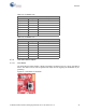
Figure 4-6. UART Connection to PSoC 4
4.3.3.3 Functionality of J6 and J7 Headers (USB-Serial)
The USB-Serial board contains two dual-inline headers (J6 and J7). These headers are both 1x7-pin
headers and include all of the GPIO and SCB connections. These headers support all of the avail-
able ports, GND, VDD, and connections to passive elements and user-input devices.
The J6 and J7 headers support 100-mil spacing, so you can solder the male connectors to connect
the USB-Serial board to any development breadboard.
Figure 4-7. J6 and J7 Connectors
Table 4-3. Pin Details of J3 Header
PSoC 4 to USB-Serial Header (J3)
Pin Signal Description
J3_01 VDD Power
J3_02 GND Ground
J3_03 P4.0 UART RX
J3_04 P4.1 UART TX
Table 4-4. Pin Details of J5 Header
USB-Serial to PSoC 4 Header (J5)
Pin Signal Description
J5_01 VDD Power
J5_02 GND Ground
J5_03 SCB.0/GPIO_6 UART TX
J5_04 SCB.4/GPIO_5 UART RX