
User manual


CY8CKIT-049-4xxx PSoC® 4 Prototyping Kit Guide, Doc. #: 001-90711 Rev. *G 33
Hardware
4.3.4 User and Passive Inputs
4.3.4.1 Push Button
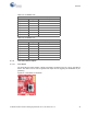
The main PSoC 4 board contains a single push button connected to the P0.7 pin on the PSoC 4
device. This button can be used for general user inputs and for triggering the bootloader for pro-
gramming.
Figure 4-8. Push Button on the Board
Table 4-5. Pin Details of J6
USB-Serial Comm/GPIO Header (J6)
Pin Signal Description
J6_01 VDD Power
J6_02 GND Ground
J6_03 S SEL Mode 0-6
J6_04 MISO/SCL Mode 0-6
J6_05 MOSI/SDA Mode 0-6
J6_06 SCLK Mode 0-6
J6_07 SCB.5/GPIO_7 Mode 0-6
Table 4-6. Pin Details of J7
USB-Serial GPIO Header (J7)
Pin Signal Description
J7_01 GND Power
J7_02 GPIO.0 Ground
J7_03 GPIO.1 Reset
J7_04 GPIO.8 GPIO
J7_05 GPIO.9 GPIO
J7_06 GPIO.10 GPIO
J7_07 GPIO.11 GPIO