
User manual


34 CY8CKIT-049-4xxx PSoC® 4 Prototyping Kit Guide, Doc. #: 001-90711 Rev. *G
Hardware
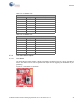
Figure 4-9. Push Button Schematic
4.3.4.2 CY8CKIT-049-4xxx LEDs
CY8CKIT-049-4xxx contains two LEDs: the amber LED, which indicates the board is power applied
and the blue LED that is directly connected to the PSoC 4 device through the pin P1.6. The blue LED
is also used to indicate the bootloader mode by rapidly blinking. The power LED is on the USB-Serial
board; if the boards are separated, the PSoC 4 section does not consume current through the power
LED.
Figure 4-10. Power LED
Figure 4-11. User LED
Figure 4-12. Power LED Connection