
User manual


CY8CKIT-049-4xxx PSoC® 4 Prototyping Kit Guide, Doc. #: 001-90711 Rev. *G 51
Code Examples
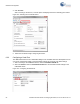
20.Click the Program button. When the firmware is programmed, observe that the LED moves from
low intensity to higher intensity in steps of 100. You can change the BRIGHTNESS_DECREASE
macro to modify the step size.
Figure 5-23. Program Button in Bootloader Host
5.4.2 Entering Bootloader Mode from the Bootloadable Application
To program the PSoC 4 device on the CY8CKIT-049 kit, you need to enter the bootloader mode
through which you can load the desired application via the Bootloader Host utility and the USB-Serial
bridge. The default bootloader in the onboard PSoC 4 enters the bootloader mode when the SW1
button is pressed during board/device power up. This method of entering the bootloader can be time
consuming and you may not prefer removing the board from the PC each time you want to program
it. You can also enter the bootloader mode using the Bootloadable component present in the appli-
cation project. When you want to enter bootloader mode, say when a button is pressed for a pre-
defined duration or a command is sent via UART, all you need to do is detect the condition to enter
bootloader mode from the bootloadable application and call the “Bootloadable_Load()” API when the
condition is met. Let us use the example in PWMExample on page 43 and modify the project to enter
bootloader mode from the bootloadable application when SW1 is pressed for more than 2 seconds.
Follow these steps to modify the project in PWMExample on page 43 to enter bootloader mode from
the application.
1. Open TopDesign.cysch of the project; drag and drop a Digital Input Pin component into the
schematic view.
Figure 5-24. Digital Input Pin Component in Component Catalog