
User manual


52 CY8CKIT-049-4xxx PSoC® 4 Prototyping Kit Guide, Doc. #: 001-90711 Rev. *G
Code Examples
2. Double-click the placed component and configure the parameters as shown in Figure 5-25 and
click OK.
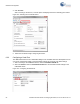
Figure 5-25. Digital Input Pin Parameter Configuration
3. In the PWMExample01.cydwr file, select P0[7] as the pin connection for SW1.
Figure 5-26. 'cydwr' Pin Settings