
User manual


CY8CKIT-050 PSoC® 5LP Development Kit Guide, Doc. # 001-65816 Rev. *E 31
Hardware
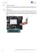
Figure 4-15. LCD Connected on P8 Connector
4.2.11 CapSense Sensors
The board layout considers the special requirements for CapSense. It has two CapSense buttons
and a 5-element CapSense slider. The CapSense buttons are connected to pins P5[6] and P5[5].
The slider elements are connected to pins P5[0:4].
The Cmod (modulation capacitor) is connected to pin P6[4] and an optional Rb (bleeder resistor) is
available on P15[4].