
User Manual Part 2

CY8CKIT-042-BLE Bluetooth® Low Energy (BLE) Pioneer Kit Guide, Doc. # 001-93731 Rev. *A 151
Advanced Topics
6.5.1 Address Selection
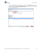
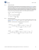
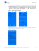
The slave address of the F-RAM device consists of three parts, as shown in Figure 6-47: slave ID,
device select, and page select. Slave ID is an F-RAM family-specific ID located in the datasheet of
the particular F-RAM device. For the device used in BLE Pioneer board (FM24V10), the slave ID is
1010b. Device select bits are set using the two physical pins A2 and A1 in the device. The setting of
these two pins on the BLE Pioneer board is controlled by resistors R32/R36 (A1) and R33/R37 (A2).
Because the memory location in F-RAM is divided into two pages of 64 KB each, the page select bit
is used to refer to one of the two pages in which the read or write operations will take place.
Figure 6-47. F-RAM I
2
C Address Byte Structure
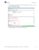
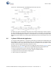
6.5.2 Write/Read Operation
The device's datasheet includes details on how to perform a write/read operation with the F-RAM.
Figure 6-48 and Figure 6-49 provide a snapshot of the write/read packet structure as a quick
reference.
Figure 6-48. F-RAM Single-Byte and Multiple-Byte Write Packet Structure