
Operating instructions


3-3 (E)
DFP-R3000
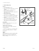
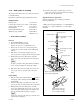
6. Remove the harness from the three hooks of cover
support.
7. Disconnect the harnesses of LED assemblies from the
connectors (CN5 and CN6) on the RD-35 board, and
pull out the harnesses from the hole of base.
8. Remove the two wire clamps from the LED support S
and remove the harness from the wire clamps.
9. Remove the two screws (PS2 x 5), and take out the
LED assembly (S side) from the LED support S.
Reassembling
Install the new LED assembly in the reverse orders of
procedures 1 through 9 above.
Adjustment after the replacement
After the replacing has been completed, perform the
following adjustments.
3-2. Light Source Adjustment (1. S side Shading Adjust-
ment → 3. Shading Compensation)
n
When the LED (S side) is replaced, reset the S side LED
lighting time stored in memory on the RD-35 board.
Refer to “1-3. Note on RD-35 Board Replacement” for
method of resetting.
3-1. Mechanical Parts Replacement
3-1-1. LED assembly (S and P sides)
The two LED assemblies use for the S (sound) and P
(picture) sides.
Required tool
L shaped hex. wrench (across ; 2 mm) : 7-770-736-03
1. LED assembly (S-side)
Removal
1. Turn the DFP-R3000 power off.
2. Remove the front panel assembly, drum cover and left
side plate.
(Refer to the section “1-2. Cabinet Removal”.)
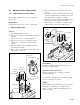
3. Remove the set screw (2 x 3) using L shaped hex.
wrench (across ; 2 mm) and take out the bearing
retainer.
4. Pull out the LED support S with LED assembly (S
side) from the drum shaft.
5. Remove the two screws (BV3 x 10 with washer) and
take out the cover support.
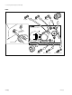
3-1. Mechanical Parts Replacement
Setscrew
(2 x 3)
BV3 x 10
(with washer)
Bearing retainer
Cover support
LED support S
Roller guide S1
<Top view>
Shaft
Drum shaft
PS2 x 5
Cover support
LED assembly
(S side)
LED support S
LED support S
Harness
Wire
clamp
<Bottom view>
Harness
Wire clamps
LED assembly
(S side)