
Operating instructions


3-4 (E)
DFP-R3000
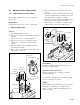
2. LED assembly (P side)
Removal
1. Turn the DFP-R3000 power off.
2. Remove the front panel assembly, drum cover and left
side plate.
(Refer to the section “1-2. Cabinet Removal”.)
3. Remove the LED assembly (S side).
(Perform the procedure 3 through 9 of “Removal of 1.
LED assembly (S side)”.
4. Remove he drum assembly.
(See the section “3-1-5. Drum assembly”.)
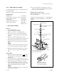
5. Remove the two screws (PSW3 x 14) to take out the
fiber (bottom side) adjustment assembly with LED
support P.
6. Remove the wire clamp from the LED support P and
remove the harness from the wire clamp.
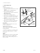
7. Remove the two screws (PS2 x 5), and take out the
LED assembly (P side) from the LED support P.
Reassembling
Install the new LED assembly in the reverse orders of
procedures 1 through 7 above.
Adjustment after the replacement
After the replacing has been completed, perform the
following adjustments.
3-2. Light Source Adjustment (1. S side Shading Adjust-
ment → 2. S side Shading Adjustment → 3. Shading
Compensation)
n
When the LED (P side) is replaced, reset the P side LED
lighting time stored in memory on the RD-35 board.
Refer to “1-3. Note on RD-35 Board Replacement” for
method of resetting.
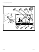
3-1. Mechanical Parts Replacement
Wire clamp
PSW3 x 14
LED support P
LED assembly (P side)
PS2 x 5
Wire clamp
Harness
Fiver (bottom)
adjustment assembly