
Operating instructions


3-5 (E)
DFP-R3000
10. Insert the roller guide S assembly (upper side), two
spacers (ø8), and one spring, and screw in the bearing
holder into the roller guide shaft.
Adjustment after the replacement
After the replacing has been completed, perform the
following adjustments.
2. Roller guide S1 height adjustment → 3-4. Film Running
Checking → 3-5. Optics Adjustment → 3-7. Error Rate
Checking
3-1-2. Roller guide S1 assembly
The height of this roller guide is to be made the reference
for the film running.
Perform the replacement and the adjustment with care.
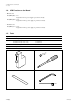
Required Tools
Cleaning cloth : 3-184-527-01
L shaped hex. wrench (across 2 mm) : 7-700-736-03
Screw locking compound : 7-432-114-11
Cleaning fluid : 9-919-573-01
Guide height adjustment tool : J-6187-860-A
Thickness gauge (10 µm) : J-6188-000-A
(Required 2 pcs.)
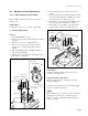
1. Removal/Reassembling
Removal
1. Turn the DFP-R3000 power off.
2. Remove the front panel assembly.
(Refer to the section “1-2. Cabinet Removal”.)
3. Remove the set screw (2 x 3) using L shaped hex.
wrench (across 2 mm), and take out the ball bearing
retainer.
4. Pull out the one roller guide S (upper side), two
spacers (ø8) and one spring from the roller guide shaft.
5. While pushing down the roller guide S assembly
(lower side), remove the E ring from the roller guide
shaft.
n
In order to protect the roller guide shaft from a damage,
be sure to wrap a vinyl tape around the tip of pliers.
6. Pull out the roller guide S assembly (lower side), two
spacers (ø8), and one spring from the roller guide
shaft.
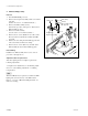
Reassembling
7. Wipe the roller guide shaft (marked by ) indicated
in the figure with a cleaning cloth moistened with the
cleaning fluid.
8. Insert the roller guide S assembly (lower side), two
spacers (ø8), and one spring into the roller guide shaft.
9. While pushing down the roller guide S assembly
(lower side), attach the E ring to the grooved portion
of the roller guide shaft by using a pair of pliers with
tip both side with which vinyl tape is wrapped.
n
Use the side wrapped with vinyl tape so that the roller
guide shaft is not damaged.
3-1. Mechanical Parts Replacement
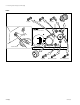
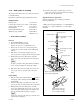
E ring
Spring
Spacers (ø8)
Spacers (ø8)
Roller guide S assembly
(lower side)
Setscrew (2 x 3)
Roller guide shaft
Spring
Roller guide S assembly
(upper side)
Bearing retainer
Wipe the shaft using cleaning cloth
moistened with cleaning fluid.
Pliers
In order to protect the roller
guide shaft from a damage,
be sure to wrap a vinyl tape.