
Operating instructions

3-6 (E)
DFP-R3000
2. Roller guide S1 height adjustment
Required Tools
Cleaning cloth : 3-184-527-01
L shaped hex. wrench (across 2 mm) : 7-700-736-03
Screw locking compound : 7-432-114-11
Cleaning fluid : 9-919-573-01
Guide height adjustment tool : J-6187-860-A
Thickness gauge (10 µm) : J-6188-000-A
(Required 2 pcs.)
Procedure
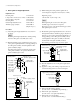
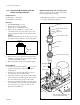
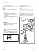
(1) Attach the guide height adjustment tool as shown in
the figure.
n
Insert the guide height adjustment tool while pushing
down the roller guide S assembly (lower side).
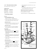
(2) Pinch the thickness gauge (10 µm) between A portion
of the guide height adjustment tool and upper flange of
the roller guide assembly, and turn lightly the roller
guide assembly by finger.
Turn the bearing retainer and adjust the height of the
roller guide assembly to the position that the roller
guide assembly begins to turn.
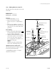
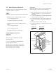
(3) While holding the bearing retainer, tighten the set
screw using the L shaped hex wrench (across 2 mm).
Tightening torque :
1.22 ±0.10 N . m (12 ±1 kgf . cm)
n
When tightening the set screw, the roller guide
assembly (upper side) may move upward.
Therefore, be sure to perform the following procedures
after tightening the set screw.
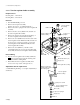
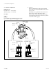
(4) Re-attach the guide height adjustment tool as shown in
the figure. Pinch the two thickness gauges (10 µm x 2)
between A portion of the guide height adjustment tool
and upper flange of the roller guide assembly, and try
to turn lightly the roller guide assembly. At this time,
check that the roller guide assembly is turned.
If not turning, perform the steps (2) and (3) again.
(5) After the adjustment, remove the guide height adjust-
ment tool.
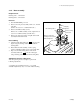
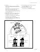
(6) Apply the coating of the locking compound to the set
screw and bearing retainer as shown in the figure.
(7) Perform the film running checking.
(See the section “3-4. Film Running Checking”.)
(8) Perform the optics adjustment.
(See the section “3-5. Optics Adjustment”.)
(9) Perform the error rate checking.
(See the section “3-7. Error Rate Checking”.)
3-1. Mechanical Parts Replacement
Upper flange
A portion
Thickness gauge (10 µm)
Guide height
adjustment tool
Setscrew (4 x 4)
Bearing retainer
Setscrew (4 x 4)
Guide height
adjustment tool
Thickness gauge (10 µm)
A portion
Upper flange
Bearing retainer
Roller guide
S assembly
Roller guide
S assembly
(lower side)
Roller guide
S assembly
(upper side)
Roller guide
S assembly
Upper flange
A portion
Two thickness gauges
(10 µm x 2)
Guide height
adjustment tool
Setscrew (4 x 4)
Bearing retainer
Setscrew (4 x 4)
Roller guide
S assembly
Apply locking compound.
Bearing retainer