
Operating instructions

3-8 (E)
DFP-R3000
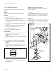
3-1-4. Tension regulator holder assembly
Required Tools
Cleaning cloth : 3-184-527-01
Cleaning fluid : 9-919-573-01
Removal
1. Turn the DFP-R3000 power off.
2. Remove the front panel assembly.
(Refer to the section “1-2. Cabinet Removal”.)
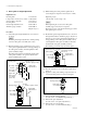
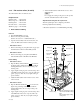
3. Remove the tension spring B of the tension regulator B
assembly.
4. Remove the three screws (PSW4 x 12) and take out
the tension regulator B assembly.
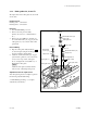
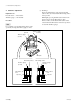
5. Remove the spring hook screw B from the flange of
the tension regulator holder B SUB assembly.
6. Remove the screw (PSW3 x 6) from the bottom of the
tension regulator holder B SUB assembly and take out
the stopper (ø3), compression spring A, spacer and
tension regulator holder B SUB assembly from the
tension regulator B assembly.
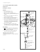
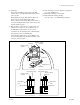
7. Remove the screw (RK4 x 8), and take out the
ornamental washer (ø4), stopper (ø4) and roller guide
S2 assembly from the tension regulator SUB assembly.
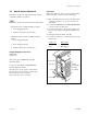
Reassembling
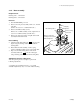
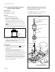
8. Wipe the tension regulator sub assembly (marked by
) as shown in the figure using the cleaning cloth
moistened with the cleaning fluid.
9. Reassemble the tension regulator assembly in the
reverse orders of procedure 1 through 7 above.
Adjustment after the replacement
3-4. Film Running Checking → 3-5. Optics Adjustment (S
and P sides)
3-1. Mechanical Parts Replacement
PSW4 x 12
Compression
spring B
Tension regulator
B assembly
Tension regulator
B SUB assembly
RK4 x 8
PSW3 x 6
Ornamental washer (ø4)
Stopper (ø4)
Stopper (ø3)
Spacer (ø6)
Spring hook screw B
Tension regulator holder
B SUB assembly
Tension regulator
SUB assembly
Compression spring A
Roller guide S2 assembly
Wipe the shafts using
cleaning cloth moistened
with cleaning fluid.