
Operating instructions

3-14 (E)
DFP-R3000
3-1. Mechanical Parts Replacement
3-1-8. CCD (S and P sides)
The S and P sides of the CCD are replaced in the same
way.
n
Perform anti-static measures when handling the CCD.
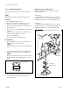
Removal
1. Turn the DFP-R3000 power off.
2. Remove the front panel assembly and optics cover.
(Refer to the section “1-2. Cabinet Removal”.)
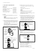
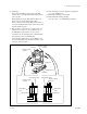
3. Disconnect the harness from the connector (CN1) on
the SE-437 board.
4. Remove the two screws (PSW2.6 x 6) fixing the SW-
437 board.
5. Remove the four screws (PS2 x 4) fixing the CCD
retainer spring assembly to take out the
SE-437 board with CCD.
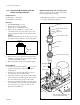
6. Remove the CCD from the SE-437 board.
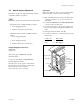
Reassembling
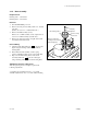
7. Mount new CCD to the socket on the SE-437 board
with CCD retainer spring assembly.
n
As the CCD glass plate is easy to break, handle it with
care.
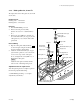
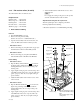
8. Attach the SE-437 board (CCD) to the CCD fitting
table (optics block) using two screws (PSW2.6 x 6).
n
Be sure to attach the SE-437 board to the place where
the CCD is fit into the CCD fitting table as shown in
figure.
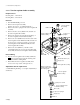
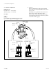
9. Fix the CCD retainer spring assembly (SE-437 board)
to the CCD fitting table (optics block) using four
screws (PS2 x 4).
Adjustment after the replacement
After the replacing has been completed, perform the
following adjustment.
CCD (S-side)
3-3. CCD Azimuth Adjustment (S side) → 3-5. Optics
Adjustment (S side) → 3-2. Light Source Adjustment (3.
Shading Compensation) → 3-7. Error Rate Checking
CCD (P side)
3-3. CCD Azimuth Adjustment (P side) → 3-5. Optics
Adjustment (P side) → 3-2. Light Source Adjustment (3.
Shading Compensation) → 3-7. Error Rate Checking
CCD
CCD fitting table
SE-437 board
CCD retainer
spring assembly
CCD
PSW2.6 x 6
PS2 x 4
PS2 x 4
Optics block
.
The illustration shows an example when S side CCD is
replaced.