
Operating instructions

3-15 (E)
DFP-R3000
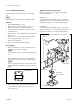
3-2. Optical Source Adjustment
Perform the optical source adjustment when the S and P
sides LED assemblies are replaced.
n
Perform the optical source adjustment with no film loaded.
. Adjustment when S side LED assembly is replaced.
1. S side shading adjustment
↓
3. Shading Compensation (S and P sides)
. Adjustment when P (S and P) side LED assembly is
replaced.
1. S side shading adjustment
↓
2. P side shading adjustment
↓
3. Shading Compensation (S and P sides)
Required Equipment and Tools
DFP-D3000
Oscilloscope
Personal computer : IBM PC/AT compatible
Terminal software
Connection cable (Supplied with DFP-R3000)
RS-232C Null modem cable
Eccentric driver (ø2-ø4) (part No. 3-702-390-01)
Eccentric driver (ø3-ø5) (part No. 3-702-391-01)
Hex wrench driver (across 2.5 mm)
Hex wrench driver (across 1.27 mm)
Preparation
Remove the OPT cover, drum cover, front panel assembly
and left side panel, and then perform the followings.
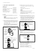
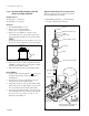
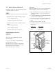
(1) Pull out the RD-35 board as shown in the figure below
so that the oscilloscope, etc. can be connected to the
TP terminal.
(2) Connect the DFP-R3000 to the DFP-D3000 READER
connector using connection cable.
(3) Connect the D-sub 9pin connector and a serial port of
PC (personal computer) using RS-232C Null modem
cable.
(4) Start up the terminal software of the PC.
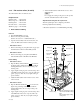
(5) Connect the oscilloscope to the following points on the
RD-35 board.
Oscilloscope RD-35 board
CH1 → TP1 (VIDEO)
CH2 → TP2 (Trigger)
3-2. Optical Source Adjustment
RD-35 board
Dsub.9P
Pull out
To DFP-D3000
To PC
TP1 (VIDEO)
TP2 (TRIG)
TP3 (CENTER)
TP4 (FG)
E6
E5