
Operating instructions

3-16 (E)
DFP-R3000
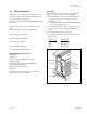
1. S side shading adjustment
Procedure
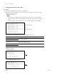
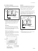
(1) Input the command C1 (press the “C” key and “1” key) from the PC keyboard at
the screen of the terminal software started and then press the Enter key.
(2) Input the command m0 from the PC keyboard and then press the Enter key.
(3) Input the command k0, 70 from the PC keyboard and then press the Enter key.
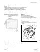
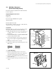
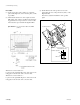
(4) Adjust the installed position of the S side LED assembly as follows so that the
output waveform of the oscilloscope CH1 is in the specification mentioned
below.
Specification : The minimum b of the CH1 output
waveform should be above 80% of
maximum a.
Adjustment :
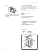
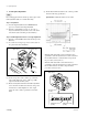
Adjustment of horizontal direction
1 Loosen the two screws A about a half turn.
2 Insert the eccentric driver (ø2-ø4) into the adjustment
hole and perform the adjustment.
Adjustment of vertical direction
1 Loosen the screw B about a half turn.
2 Turn the bearing retainer to adjust.
(5) After adjustment has been completed, tighten the loosened screws.
Check that the output waveform of the oscilloscope CH1 after tightening meets
the specification in the above step (4).
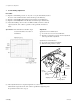
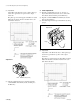
3-2. Optical Source Adjustment
Bearing retainer
Drum
assembly
Screw B
Screws A
Adjusting hole
LED assembly
(S side)
Horizontal
direction
Vertical
direction