
Operating instructions

3-19 (E)
DFP-R3000
3-3. CCD Bias Adjustment
(SE-437 board Adjustment)
Perform the CCD bias adjustment when CCD and SE-437
board are replaced.
Required Equipment and Tools
DFP-D3000
Oscilloscope
Personal computer: IBM PC/AT compatible
Terminal software
RS-232C Null modem cable
Paper (Thickness ; 0.5 mm or more, size ; 100 x 100 mm)
: The paper is able to shut off the light.
Preparation
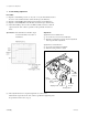
Remove the OPT cover, drum cover, front panel assembly
and left side panel, and then perform the followings.
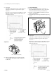
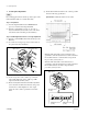
(1) Pull out the RD-35 board as shown in the figure below
so that the oscilloscope, etc. can be connected to the
TP terminal.
(2) Connect the DFP-R3000 to the DFP-D3000 READER
connector using connection cable.
(3) Connect the D-sub 9pin connector and a serial port of
PC (personal computer) using RS-232C Null modem
cable.
(4) Start up the terminal software of the PC.
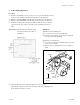
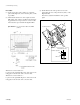
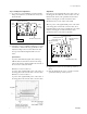
(5) Connect the oscilloscope to the following points on the
RD-35 board.
Oscilloscope RD-35 board
CH1 → TP1 (VIDEO)
CH2 → TP2 (Trigger)
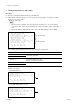
1. S side adjustment
(1) Input the command C1 (press the “C” key and “1”
key) from the PC keyboard at the screen of the termi-
nal software started and then press the Enter key.
(2) Input the command m0 from the PC keyboard and then
press the Enter key.
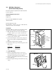
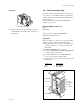
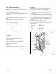
(3) Shut off the light incident upon the CCD lens by using
a paper.
3-3. CCD Bias Adjustment (SE-437 board Adjustment)
Optics block
Lens
Paper
RD-35 board
Dsub.9P
Pull out
To DFP-D3000
To PC
TP1 (VIDEO)
TP2 (TRIG)
TP3 (CENTER)
TP4 (FG)
E6
E5
Optics block
Lens
Paper