
Operating instructions

3-23 (E)
DFP-R3000
3-5. Optics Adjustment
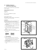
Perform the optics adjustment when roller guides (S1, S2,
S3 and T1), tension regulator holder and CCD (SE-437
board) (S and P sides) are replaced.
Perform the optics adjustment with DFP-R3000 installed to
the projector.
Adjustment items (Procedure of S and P sides are the
same.)
CCD magnification and focus rough adjustment
↓
CCD position rough adjustment
↓
CCD azimuth rough adjustment
↓
CCD focus fine adjustment
↓
CCD azimuth fine adjustment
↓
CCD magnification fine adjustment
Required Equipment and Tools
DFP-D3000
Oscilloscope
Personal computer : IBM PC/AT compatible
Terminal software
Connection cable (Supplied with DFP-R3000)
RS-232C Null modem cable
Alignment film (with data sheet)
Filter tool
Eccentric driver (ø1.5-ø2.5) (part No. J-6187-880-A)
Hex wrench driver (across 2.5 mm)
Preparation
Remove the OPT cover, drum cover, front panel assembly
and left side panel, and then perform the followings.
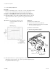
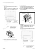
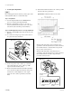
(1) Pull out the RD-35 board as shown in the figure below
so that the oscilloscope, etc. can be connected to the
TP terminal.
(2) Connect the DFP-R3000 to the DFP-D3000 READER
connector using connection cable.
(3) Connect the D-sub 9pin connector and a serial port of
PC (personal computer) using RS-232C Null modem
cable.
(4) Start up the terminal software of the PC.
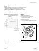
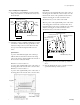
(5) Connect the oscilloscope to the following points on the
RD-35 board.
Oscilloscope RD-35 board
CH1 → TP1 (VIDEO)
CH2 → TP2 (Trigger)
CH3 → TP3 (Center)
3-5. Optics Adjustment
RD-35 board
Dsub.9P
Pull out
To DFP-D3000
To PC
TP1 (VIDEO)
TP2 (TRIG)
TP3 (CENTER)
TP4 (FG)
E6
E5