
Operating instructions

3-25 (E)
DFP-R3000
Step 3. CCD position adjustment
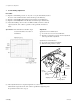
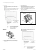
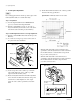
(1) Loosen the two screws (PSW2.6 x 6) and four CCD
fixing screws (PS2 x 4) on the SE-437 board (S side)
abut a half turn.
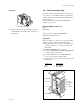
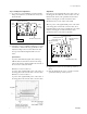
(2) Adjust the position to install the CCD using a eccentric
screwdriver so that the following specification is met.
Adjust according to the correction value in the data
sheet provided with the alignment film as shown
below.
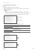
Specification :
A portion of the film data signal of the oscilloscope
CH1 should be deviated from center B of the rising
pulse of the reference signal of CH2 for the amount of
the S correction value (±0.1 mark).
When the S correction value is + :
A portion of the signal leads B portion of the center of
the rising pulse for the amount of the correction value.
When the S correction value is _ :
A portion of the signal trails B portion of the center of
the rising pulse for the amount of the correction value.
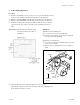
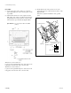
Adjustment
If A portion of the signal leads B portion of the center of
the rising pulse more than the correction value, move the
CCD from the outside of the optical block to the inside.
Adjust by inserting the eccentric screwdriver in the
adjustment hole a on the outside of the CCD.
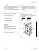
When A portion of the signal trails B portion of the center
of the rising pulse more than the correction value, move
the CCD from the inside of the optical block to the outside.
Adjust by inserting the eccentric screwdriver in the
adjustment hole b on the inside of the CCD.
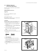
(3) Tighten the six screws loosened at the procedure (1)
above.
(4) After the tightening the screws, re-check to meet the
specification in the procedure (2) above.
3-5. Optics Adjustment
CCD
fixing
screws
SE-437 board (S side)
Screws (PS 2.6 x 5)
CCD
fixing
screws
CCD fixing screws
Adjustment hole b
(In side)
SE-437 board (S side)
Screws (PS 2.6 x 5)
CCD fixing screw
Adjustment hole a
(Out side)