
Operating instructions


3-30 (E)
DFP-R3000
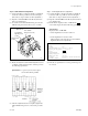
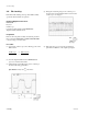
Step 4. CCD azimuth rough adjustment
(1) Input the command m110 from the PC keyboard and
then press the Enter key.
(2) Loosen the P side azimuth fixing screw about a half
turn using hex wrench driver (across 2.5 mm).
(3) Rotate and adjust the CCD azimuth adjustment screws
so that the output waveform of the oscilloscope meets
the following specification.
Specification : A portion (second) of the output
waveform should be parallel.
(4) After the adjustment has been completed, tighten the
CCD azimuth fixing screw loosened at the procedure
(2) above.
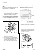
Step 5. CCD focus fine adjustment
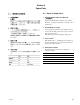
(1) Connect the filter tool between the TP1 on the RD-35
board and oscilloscope CH1 as shown in the figure.
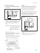
(2) Input the command m100 from the PC keyboard and
then press the Enter key.
(3) Rotate and adjust the second and third CCD adjust-
ment screws from the mechanical deck chassis so that
the ◊ part (eye patterns) of the output waveform (TP1)
of the oscilloscope CH1 becomes maximum.
(4) Tighten the loosened two hexagon cap screws at the
bottom of the optics block in “procedure (3) of Step
2”, and check that the ◊ portions (eye patterns) do not
change.
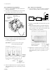
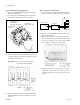
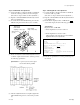
3-5. Optics Adjustment
TP4
E5
TP3
TP1
TP2
E6
EJ
TP J1
RD-35 board
Oscilloscope
Filter tool
W2
W1
CH1
Optics block
CCD azimuth
adjusting screw (P side)
CCD azimuth
fixing screw (P side)
SE-437 board
(P side)