
Operating instructions


3-31 (E)
DFP-R3000
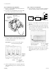
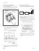
Step 6. CCD azimuth fine adjustment
(1) Connect the filter tool between the TP1 on the RD-35
board and oscilloscope CH1 as shown in the figure.
(The same as “Step 5. CCD focus fine adjustment”.)
(2) Input the command m110 from the PC keyboard and
then press the Enter key.
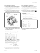
(3) Loosen the P side CCD azimuth fixing screw about a
half turn using hex wrench driver (across 2.5 mm).
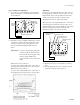
(4) Rotate and adjust the CCD azimuth adjustment screws
so that the output waveform of the oscilloscope meets
the following specification.
Specification : A portion (second) of the output
waveform should be parallel.
(5) After the adjustment has been completed, tighten the
CCD azimuth fixing screw loosened at the procedure
(3).
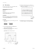
Step 7. CCD magnification fine adjustment
(1) Connect the filter tool between the TP1 on the RD-35
board and oscilloscope CH1.
(The same as “Step 5. CCD focus fine adjustment”.)
(2) Input the command w1 from the PC keyboard and then
press the Enter key.
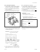
(3) Check that the displayed value of “LPF 2T1T” (
section in the figure) meets the following specification.
Specification :
Displayed value of LPF 2TIT
= P side magnification correction value
*
±8
* P side magnification correction value :
Value indicated on the data sheet provided with the
alignment film used in adjustments.
(4) If the above specification is not met, perform steps 2 to
6 to meet it.
3-5. Optics Adjustment
RF OFSET : 00F3
RF GAIN : 0024
VCO OFSET : 1D80
2TEDGE 1TEDGE LENGTH CL2T A2 : E2A1 E3C3 0906 E2A2 C3
RAW_VCO LP_32VCO CALC_FS ERR : 0051 0A1C 0886 0190
LPF_2T1T : 0960
DIF_LEVEL HANE_LEVEL : 0960 01FF
3T_PEAK_AVE PK_GAIN_LIM : 0275 005A
HIKIKOMI [5T/3T] [AFC] : [OK] [OK]
3T LOCATION : E2D5 E2F3 E317 E33B E35D E37B E39F E3C3
3T PATTERN 1..DETECTED : 1111 1110
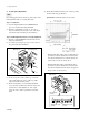
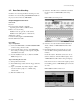
Optics block
CCD azimuth
adjusting screw (P side)
CCD azimuth
fixing screw (P side)
SE-437 board
(P side)