• Direct Vent Freestanding Stove • Natural Gas or Propane • Vent Horizontally or Vertically • Standard Residential • Mobile Home Approved Tested and Listed by ANSI Z21.88 CSA 2.33 WARNING: - • • • • - If the information in these instructions is not followed exactly, a fire or explosion may result causing property damage, personal injury or loss of life. Do not store or use gasoline or other flammable vapors and liquids in the vicinity of this or any other appliance.
Introduction 2 Introduction We welcome you as a new owner of a Cypress GS2 stove. In purchasing a Cypress you have joined the growing ranks of concerned individuals whose selection of an energy system reflects both a concern for the environment and aesthetics. The Cypress is one of the finest home heaters the world over. This manual will explain the installation, operation, and maintenance of this stove.
Table of Contents 3 Contents Introduction ...................................................... 2 Important Information ...................................... 2 Listing Details ................................................... 2 Vent Termination Requirements (see illustration below) .......................................... 23 Steps for Finalizing the Installation ............. 24 IAS (ICBO) Approval ............................................. 2 Features: ..........................................
Safety Precautions 4 • IF YOU SMELL GAS: * Do not light any appliance * Extinguish any open flame * Do not touch any electrical switch or plug or unplug anything * Open windows and vacate building * Call gas supplier from neighbor's house, if not reached, call fire department • • This unit must be installed by a qualified installer to prevent the possibility of an explosion. Your dealer will know the requirements in your area and can inform you of those people considered qualified.
Safety Precautions • Do not place clothing or other flammable items on or near the heater. Because this heater can be controlled by a thermostat there is a possibility of the heater turning on and igniting any items placed on or near it. • Light the heater using the built-in igniter. Do not use matches or any other external device to light your heater. • Allow the heater to cool before carrying out any maintenance or cleaning.
Specifications 6 Features: Installation Options: - Works During Power Outages (battery backup system) - Freestanding Stove - High Efficiency - Horizontal or Vertical Vent - Convenient Operating Controls - Residential or Mobile Home - Variable-Rate Heat Output - Straight or Corner Placement - Accent Light - Bedroom Approved Heating Specifications Approximate Heating Capacity (in square feet)* ........... 1,200 – 2,000 with Blower, 800 – 1,600 Without Maximum Input .....................
Installation (for qualified installers only) 7 Installation Warnings ! ! ! ! ! ! ! ! Failure to follow all of the requirements may result in property damage, bodily injury, or even death. This heater must be installed by a qualified installer who has gone through a training program for the installation of direct vent gas appliances. This appliance must be installed in accordance with all local codes, if any; if not, in U.S.A. follow ANSI Z223.1 and NFPA 54(88), in Canada follow CSA B149.1.
Installation (for qualified installers only) 8 Installation Hints Recommended Optional Equipment Installation Order: -- Rear Vent Conversion (if applicable) -- GreenSmart Remote -- Blower -- LP Conversion and other optional equipment (fireback) Install the media (logs, driftwood, or stone set) last - they are fragile. When determining the location of the stove, locate the wall studs (for horizontal penetrations) and ceiling trusses (for vertical penetrations).
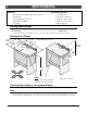
Installation (for qualified installers only) 9 Top to Rear Vent Modification NOTE: The rear vent parts are included in the Minimum Vent Kit “D” (sku 96200317). If using the rear vent configuration, make sure to review vent configuration before proceeding.
Installation (for qualified installers only) 10 Heater Placement Requirements • • Heater must be installed on a level surface capable of supporting the heater and vent. Due to the high temperature, the heater should be located out of traffic and away from furniture and draperies.
Installation (for qualified installers only) 11 Optional Wall Switch or Thermostat Installation Do not connect 110-120 VAC to the gas control valve or wiring system of this stove. The switch must be installed by a qualified installer. Caution: Label all wires prior to disconnection when servicing controls. Wiring errors can cause improper and dangerous operation. Note: When using a GreenSmart™ remote, use the receiver for on/off operation (do not use a wall switch or thermostat).
Installation (for qualified installers only) 12 Gas Line Installation ! ! • • • • • The gas line must be installed in accordance with all local codes, if any; if not, follow current ANSI Z223.1 or NFPA 54 in the USA and the current CSA B149.1 in Canada. The heater and gas control valve must be disconnected from the gas supply piping during any pressure testing of that system at test pressures in excess of 1/2 psig (3.45 kPA). For pressures under 1/2 psig (3.
Installation (for qualified installers only) 13 Vent Requirements • The gas appliance and vent system must be vented directly to the outside of the building, and never be attached to a chimney serving a separate solid fuel or gas-burning appliance. Each direct vent gas appliance must use its own separate vent system. In addition to the requirements listed here, follow the requirements provided with the vent. When the vent passes through a wall a wall thimble is required.
Installation (for qualified installers only) 14 Approved Vent Configurations Exhaust Restrictor Position • An exhaust restrictor is built into the appliance to control the flow rate of exhaust gases. This ensures proper flames for the wide variety of vent configurations. Depending upon the vent configuration, you may be required to adjust the restrictor position. The charts for approved vent configurations describe which position the vent restrictor should be in.
Installation (for qualified installers only) 15 Closing the Diffuser (for top vent configurations only) IMPORTANT NOTE: The diffuser can be easily closed with no vent in place. Consult the vent configuration charts to determine diffuser position. If the diffuser needs to be in the closed position, adjust the diffuser prior to installing vent. • To close the diffuser, reach into the vent starter section and bend the diffuser back (see photos below).
Installation (for qualified installers only) 16 Exhaust Restrictor Extender (for rear vent configurations only) • Follow the directions below to install the exhaust restrictor extender. Remove these two screws on the exhaust restrictor. Firebo Back W all of F x Roo f irebox Exhaust Restrictor Extender Plate (included in the rear vent kits) Use the screws to attach the extender to the exhaust restrictor.
Installation (for qualified installers only) 17 Rear Vent Configuration with No Rise • • • • • • Use the minimum vent kit “D” from Travis Industries (SKU 96200317). This kit contains the following components used to vent the stove through a typical exterior wall: -- Travis Thimble (unique to this stove) -- Wall Cover (Black) -- Pipe Section (3.9”) -- Pipe Section (6”) -- Snorkel Cap (14” – unique to this stove) -- Rear Vent Conversion Parts (cover plates, starter sections, etc.
Installation (for qualified installers only) 18 Rear Vent Configuration with Horizontal Termination 16' max (4.8m) 15 feet (4.5m) 10 feet (3m) Exhaust Restrictor Position #5 Exhaust Restrictor Extender Installed 5 feet (1.5m) • Use the rear vent conversion from Travis Industries (SKU 94400998). Use 8” Diameter Vent Horizontal sections require a ¼” (6mm) rise every 12” (305mm) of travel. A maximum of three (3) 45° or 90° elbows may be used.
Installation (for qualified installers only) 19 • • • • Use the rear vent conversion from Travis Industries (SKU 94400998). Use 8” Diameter Vent Horizontal sections require a ¼” (6mm) rise every 12” (305mm) of travel. A maximum of three (3) 45° or 90° elbows may be used. Of these elbows, only one (1) may be a horizontal elbow (see illustration). The termination must fall within the shaded area shown in the chart. Use the indicated restrictor position.
Installation (for qualified installers only) 20 Rear Vent Configuration Vented into Fireplace with Co-Linear Adapter • • • • Attach the Co-Linear adapter directly to the back of the stove. Use UL 441 or 1775 gas liners to vent the appliance through a code-conforming masonry or metal (zc) fireplace. All clearances to combustibles must be met and the flex vent must be vented through a non-combustible fireplace chimney.
Installation (for qualified installers only) 21 Top Vent Configuration with Vertical Termination 24 ' max (7.3m) 20 feet (6m) 15 feet (4.5m) 10 feet (3m) 0 feet • Use 6-5/8” Diameter Vent Horizontal sections require a ¼” (6mm) rise every 12” (305mm) of travel. A maximum of four (4) 45° or 90° elbows may be used. Of these elbows, only one (1) may be a horizontal elbow (see illustration). The termination must fall within the shaded area shown in the chart.
Installation (for qualified installers only) 22 Top Vent Configuration with Horizontal Termination 24 ' max (7.3m) 20 feet (6m) 15 feet (4.5m) 10 feet (3m) 0 feet • Use 6-5/8” Diameter Vent Horizontal sections require a ¼” (6mm) rise every 12” (305mm) of travel. A maximum of four (4) 45° or 90° elbows may be used. Of these elbows, only one (1) may be a horizontal elbow (see illustration). The termination must fall within the shaded area shown in the chart.
Installation (for qualified installers only) 23 Vent Termination Requirements (see illustration below) ! Venting terminals shall not be recessed into a wall or siding. A B C Minimum 9" (229mm) clearance from any door or window Minimum 12" (305mm) above any grade, veranda, porch, deck or balcony Minimum 1" (25mm) from outside corner walls NOTE: Clearance in accordance with local installation codes and the requirements of the gas supplier.
Installation (for qualified installers only) 24 Steps for Finalizing the Installation 1. Remove the glass (see page 26). NOTE: set. If using propane (LP) convert the appliance prior to installing the logs, driftwood, or stone 2. We recommend you purge the gas line at this time (with the glass removed). This allows gas to be detected once it enters the firebox, ensuring gas does not build up. 3. Make sure the accent light works correctly.
Installation (for qualified installers only) 9. 25 Check the air shutter following the directions below. Air Shutter Adjustment Let the heater burn for fifteen minutes (make sure the media and glass are in place). The flames should be yellow with no sooting. Adjust the air shutter, if necessary, to achieve the correct looking flame. Correct Flames should be blue at the base, yellow-orange on the top. Not Enough Air If the flames are too tall or sooty on the ends, open the air shutter.
Finalizing the Installation (for qualified installers only) 26 Face and Glass Removal ! Make sure the gas control valve is “OFF” and the heater is cool prior to conducting service. Phillips Screwdriver b a Open the two latches holding the glass frame in place - follow the directions shown below Remove the two screws securing the stove top. Lift the stove top off the stove and place it aside.
Finalizing the Installation (for qualified installers only) 27 Glass Frame Removal and Installation (continued) The latch can come loose from glass frame anchor. This occurs when it is turned 1/4 turn when it is disengaged. Follow the directions below to re-install the latch if it becomes loose. Hold the latch at an angle and insert it into the slot on the glass frame anchor. Latch NOTE: this slot may be at a different angle than illustrated.
Finalizing the Installation (for qualified installers only) 28 Media Installation (Log, Stone, or Driftwood) ! The logs are fragile, especially after being exposed to heat. Make sure the gas control valve is “OFF” and the heater is cool prior to conducting service. Failure to position the parts in accordance with these diagrams or failure to use only parts specifically approved with this appliance may result in property damage or personal injury.
Operation 29 Before You Begin Warning: Warning: Read this entire manual before you use your new stove (especially the section "Safety Precautions" on pages 4 & 5). Failure to follow the instructions may result in property damage, bodily injury, or even death. Do not operate appliance with the glass front removed, cracked or broken. Replacement of the glass should be done by a licensed or qualified service person.
Operation 30 Starting the Stove for the First Time Burn the heater at a high setting with the blower off for an extended period (up to 48 hours). This will cure the painted surfaces. Fumes from the paint curing and oil burning off the steel will occur. This is normal. We recommend opening a window to vent the room. Condensation may appear on the glass each time you start the stove - this is normal. Blue Flames will occur on the stove when it first comes on.
Operation 31 Accent Light This stove has a built-in accent light that may be turned on and off and dimmed to your preference. Turn the knob to achieve the desired light output. HIGH OFF LOW ACCENT LIGHT Adjusting the Optional Blower Speed The blower helps transfer heat from the heater into the room. It will not turn on until the heater is up to temperature (approximately 15 minutes after starting). See the illustration below for instructions on adjusting the blower speed.
Operation 32 Normal Operating Sounds Extinction Pops It is not unusual, especially on Propane The appliance may creak with change (LP) appliances, to experience a "pop" of temperature -- THIS IS NORMAL. when the burner is shut off. Pilot Flame Blowers The pilot flame will make a clicking This heater has optional blowers to push sound when starting up. When on, it heated air into the room. You will hear the will make a slight whisper sound.
Maintenance 33 (for qualified service personnel only) Maintaining Your Stove's Appearance Painted Surfaces • Painted surfaces should be cleaned with a duster. If scratches occur, lightly sand the area with fine sandpaper. Clean the area and, with the stove cool, apply one or two thin coats of stove paint to the area (mask the area to avoid overspray). Allow the stove to dry, then turn the stove on to cure the paint (1 hour on medium).
Maintenance 34 (for qualified service personnel only) Accent Light Replacement An accent light is included in your stove to provide additional lighting. To replace the bulb, follow the directions below: Disconnect stove from power. Shut off gas to the stove. Make sure the stove is cool before proceeding (15 minutes). Remove the stove top and place it aside (see page 26). Remove the four screws securing the accent light cover. Place the cover to aside.
Maintenance 35 (for qualified service personnel only) Yearly Service Procedure • 1. 2. 3. 4. Failure to inspect and maintain the stove may lead to improper combustion and a potentially dangerous situation. We recommend the following procedures be done by a qualified technician. Turn the pilot flame to continuous. It should touch approximately 3/8" of the top of the flame sensor. If it does not, contact your dealer for service. Shut off gas to the stove and let it cool for 15 minutes.
Maintenance 36 (for qualified service personnel only) Troubleshooting Table Problem: Possible Cause: Main Burners Will Not Start Heater Beeps The ON/OFF switch is turned to "OFF" The remote control is not working correctly The thermostat is disconnected or set too low No Propane in Tank Turn the ON/OFF switch to "ON" See the remote control instructions See "Thermostat Operation" Check Tank Level The power backup batteries are dead (heater will beep once repeatedly) Replace the batteries (see page 3
Report No. 100162727PRT-001 Control No. 4000515 Cypress GS Vented Gas Fireplace Heater Certified for USA and Canada Tested to: ANSI Z21.88-2009/CSA 2.33-2009 “Vented Gas Fireplace Heaters”, CGA 2.17-M91, UL 307b-2006 “Gas Burning Heating Appliances for Manufactured Homes”, and CSA P.4.1-09. This appliance must be installed in accordance with local codes, if any; if none, follow the National Fuel Gas Code, ANSI Z223.1/NFPA 54, or Natural Gas and Propane Installation Codes, CSA B149.1.
Limited Lifetime Warranty 38 Register your TRAVIS INDUSTRIES, INC. Limited 7 Year Warranty online at traviswarranty.com, or complete the enclosed Warranty card and mail it within ten (10) days of the appliance purchase date to: TRAVIS INDUSTRIES, INC., 4800 Harbour Pointe Blvd. SW, Mukilteo, WA 98275. TRAVIS INDUSTRIES, INC. warrants this gas appliance (appliance is defined as the equipment manufactured by Travis Industries, Inc.
Optional Equipment (for qualified installers only) 39 LP Conversion Instructions WARNING This conversion kit shall be installed by a qualified service agency in accordance with the manufacturer’s instructions and all applicable codes and requirements of the authority having jurisdiction. If the information in these instructions are not followed exactly, a fire, explosion or production of carbon monoxide may result causing property damage, personal injury or loss of life.
Optional Equipment 40 4 Discard the manifold cover (see below). 5 Install the LP (propane) orifices.
Optional Equipment 6 (for qualified installers only) 41 Install the LP (propane) manifold cover included in owner’s pack (see illustration below).
Optional Equipment (for qualified installers only) 7. Install the LP pilot orifice following the directions below. (a) Use a 7/16” open-end wrench to remove the pilot hood. (b) Remove and discard the Natural Gas (NG) orifice. Place the LP orifice in the pilot assembly then replace the pilot hood, tightening the pilot hood until it is snug (do not over-tighten). Natural Gas Orifice = .020N (3way) .018N (2way) .020N or .018N LP (Propane) Orifce = .014LP .
Optional Equipment (for qualified installers only) 43 Before replacing the burner, check the instructions for the type of media you are using (log, stone, or driftwood). Depending upon media type, you may be required to modify the stove. 8 Replace the burner, making sure it is correctly seated. Replace the ember trays. 9 Replace the regulator following the instructions included with the regulator kit. Remove and discard the screws (see “a” below) holding the stock regulator in place (see “b” below).
Optional Equipment 44 (for qualified installers only) GS2 Remote Installation Packing List Transmitter Battery Box Remote Wall Mount with Attachment Screws and Anchors Stepper Motor Torx Wrench Remote Control DVD GSR2 IFC Split-flow Harness (attached to IFC) System Jumper (attached to IFC) Battery Box Harness (attached to IFC) Fan/Light Harness (attached to IFC) (2) Jumper Wires (2) 4” Cable Ties Warnings Turn off power to the heater (unplug or turn off at the breaker).
Optional Equipment (for qualified installers only) 45 Base Wiring Diagram Caution: Label all wires prior to disconnection when servicing controls. Wiring errors can cause improper and dangerous operation. 2.5 Amp Fuse Accessory Power Accent Light Rheostat Blower Hookup Black White Green 120 VAC Power In Accent Light (s) Appliance Ground 3.
Optional Equipment (for qualified installers only) GS2 Remote Wiring Diagram Accessory Power White White Black Black Accent Light (s) Optional Blower(s) 2.5 Amp Fuse Appliance Ground 2.5 Amp Fuse 3.
Optional Equipment (for qualified installers only) 47 Installation 1. Remove the Comfort Control–Battery Plate from the control panel (keep the screws). 2. Remove the control panel and place face-down in front of the heater (keep the screws). 3. Disconnect the comfort control and battery backup wires. 4. Remove and place aside the Comfort Control-Battery Plate with harness (the batteries and assembly may be kept for spare parts).
Optional Equipment (for qualified installers only) 5. Remove the rear panel from the heater and set aside. It is held in place with seven screws. Screw Locations 6. Disconnect input power. 7. Pull the base IFC to the rear of the stove to access the wiring (it is held in place with Velcro).
Optional Equipment (for qualified installers only) 49 8. Disconnect the following: Main harness Power (3 wires) Pilot connections (slide silicone tubing up) On/Off wires 9. Remove and place aside the base IFC (it may be kept for spare parts). 10. Remove the on/off switch by prying it out. Disconnect the wires. 11. Push the wires back into the holder to conceal them.
Optional Equipment (for qualified installers only) 12. Remove and discard the screws (see “a” below) holding the stock regulator in place (see “b” below). Remove and discard the stock regulator, spring, and gasket (see “c” below). a T-20 Torx or Slotted Screwdriver b c d 13. The stepper motor (adjustable regulator) has an installation sheet included with it – make sure to follow all of the directions.
Optional Equipment 51 (for qualified installers only) Instructions for Using the Optional Blower with GS2 Remote When using the GreenSmart™ 2 remote, the power for the blower will be routed through the fuse and IFC, bypassing the rheostat and snap disc included with the blower kit. Order of Installation Install the blower assemblies with the IFC removed (see instructions included with the blower for details).
Optional Equipment (for qualified installers only) 14. Wire the accent light for remote operation. When using the GreenSmart™ 2 remote, the power for the accent light(s) will be routed through the fuse and IFC, bypassing the rheostat. Order of Installation Connect the wiring with the IFC removed as shown below. Attach the power input to the IFC after the IFC is placed in location (see “a” below).
Optional Equipment (for qualified installers only) 53 16.
Optional Equipment (for qualified installers only) 17. Disconnect the IPI/CP switch from IPI/CP wires. Attach one of the jumper wires to the two wires. Discard the IPI/CP switch. 18. Remove the IPI/CPI switch and place aside (may be kept for spare parts). 19. Connect the accent light wires to the GSR2 IFC. NOTE: If using a blower, connect the power input to the GSR2 IFC.
Optional Equipment (for qualified installers only) 55 20. Connect the battery box power molex connector to the main harness molex connector. 21. Route the battery box harness through the control panel and attach to the battery box. 22. Place the IFC in location inside the heater and attach using the supplied velcro tape. 23. Use the two included cable ties to make sure all wiring is secure and does not contact any hot or moving parts.
Optional Equipment (for qualified installers only) 24. Re-attach the control panel. 25. Attach the battery box to the control panel using the screws removed in step 2.
Optional Equipment (for qualified installers only) 57 26. Re-connect the input power. 27. Replace the rear panel and restore the stove to the correct configuration (turn on power and gas). See the instructions included with the remote for synchronizing the remote and the operating instructions.
Index 58 Index Accent Light ..................................................... 31 Accent Light Replacement ............................... 34 Additional Items Required .................................. 7 Adjusting the Flame Height .............................. 30 Adjusting the Optional Blower Speed .............. 31 Approved Vent Configurations ......................... 14 Battery Replacement........................................ 33 Before You Begin .............................................