
Datasheet

CY8C20xx6A/H CapSense Design Guide Doc. No. 001-65973 Rev. *A 32
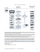
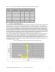
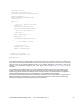
Figure 4-6. Tuning the CSD User Module
Measure C
p
of sensors
using EP64134
Start
If max C
p
< 45pF set
Idac
Rang
e to 4X. Otherwise
set to 8X.
Enable
Autocalibration
Set
Precharge Source
to
PRS
Set
Prescaler
according to
Table 4-1
Set
Resolution
according
to Figure 4-7 and
Table 4-2
Set
Scanning Speed
to
Fast
Set
PRS Resolution
to 12
bits if scan time > 380 µs
according to Table 4-3.
Otherwise set to 8 bits.
Set
Shield
Electrode Out
according to needs
of design
Establish digital
communication interface and
obtain raw counts from each
sensor during finger
activation cycle, for example.
Figure 4-8
Is SNR from all sensors
> 5:1?
Increase
Resolution
and/or
experiment with
Scanning
Speed
until optimal SNR is
obtained
Is SNR from all sensors
> 5:1?
Revise PCB design
according to AN2292 and
AN2318
No
No
Does scan time meet
design requirements?
Yes
Yes
Reduce
Resolution
or
used faster
Scanning
Speed
No
Yes
Set
Finger Threshold
to
75% of signal
Set
Noise Threshold
to
40% of signal
Set
BaselineUpdate
Threshold
to double
the Noise Threshold
Set
Sensors Autoreset
according to needs of
design
Set
Hysteresis
to 15%
of signal
Set
Debounce
according to needs of
design
Set
Negative Noise
Threshold
to same
value as Noise
Threshold
Set
Low Baseline
Reset
to 10
Start
Hardware
Parameters
High-Level API
Parameters
Hardware parameters configure the hardware that the CSD method uses to convert the physical capacitance of each
sensor into a digital code. This section describes these parameters and provides guidance on how each should be
tuned based on system characteristics and other parameters.
By default, hardware parameters are global settings that apply to all CapSense sensors in a design. In designs where
total parasitic capacitance of each sensor (C
P
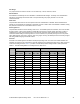
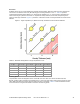
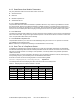
Table 4-1
), sensor sensitivity, or both vary over a wide range, there may not be
global hardware parameter settings that are suitable for all sensors. In such cases, the SetIdacValue(i),
SetPrescaler(i), and SetScanMode(i) API functions can be used to configure the respective hardware parameters for
each sensor where (i) is the sensor index prior to calling the ScanSensor(i) API function.
and Table 4-3 provide tuning recommendations for several key hardware parameters based on sensor C
P
.
C
P
values depend on characteristics of the PSoC, PCB layout, and proximity of other components in the assembled
product. That being the case, C
P
must be measured in its original position with the system in its final assembled
state; that is, in the same enclosure and with the same overlay as the system will have in service. The best way to
measure C
P
is to use the code example titled Measuring Absolute Sensor Capacitance with a CY8C20xx6 CapSense
Controller (EP64134). This project measures the absolute capacitance of each sensor in a system using the PSoC
itself, thus taking into account all factors affecting C
P
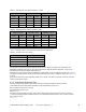
ShieldElectrodeOut
. See the documentation associated with the code example for
instructions on its setup and use
Enable the ShieldEletrodeout for this design.