
Datasheet
CY8C20xx6A/H CapSense Design Guide Doc. No. 001-65973 Rev. *A 36
4.3.2 Set High-Level Parameters
The following recommendations are a starting place for selecting the optimal parameter settings:
Finger Threshold: Set to 75 percent of Raw Counts with sensor ON
Noise Threshold: Set to 40 percent of Raw Counts with sensor OFF
Negative Noise Threshold: Set equal to (Noise Threshold/2)
Baseline Update Threshold: Set to two times Noise Threshold
Hysteresis: Set to 15 percent of Raw Counts with sensor ON
Low Baseline Reset: Set to 50
Sensors Autoreset: Based on design requirements
Debounce: Based on design requirements
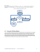
4.4 Using the SmartSense User Module
SmartSense enables you to create a CapSense design that requires no tuning, as long as the sensor parasitic
capacitance is in the range from 5 pF to 45 pF with a minimum 0.1-pF finger touch. You can create a SmartSense
design by using the SmartSense User Module in PSoC Designer 5.1. This section also shows you how to migrate an
existing CSD CapSense design to SmartSense.
4.4.1 Guidelines for SmartSense
Follow these guidelines when using the SmartSense User Module in an application:
SmartSense requires capacitive user interface design to follow the layout and system design best practices
documented in the previous sections of this design guide.
All of the CSD User Module parameters (such as iDAC value, prescaler period, clock divider, scan speed,
resolution) are determined at run time by the SmartSense User Module. You should not use APIs that modify
these CSD parameters in firmware, unless you know exactly what effect it has in your design.
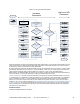
To migrate an existing design from CSD to SmartSense,
Ensure that all APIs that set or modify the CSD parameters are first removed from the program.
Ensure that the parasitic capacitance of all CapSense sensors in the design is between 5 pF and 45p F over
environmental and PCB production process variations.
Make sure recommended C
MOD
capacitor (X7R, 2.2-nF, voltage rating more than 5 V) is connected to the
C
MOD
4.4.2 Understanding the Difference
port pin selected in the user module wizard.
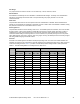
The differences between the SmartSense User Module and the standard CSD User Module are:
The SmartSense User Module supports APIs that a standard CSD User Module supports. Thus, no change is
required in placing, configuring, starting, or calling other APIs except the User Module instance name.
There is no need to set any User Module parameters for tuning, as all the parameters related to tuning are
automatically set at run time by the SmartSense User Module.
The C
MOD
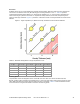
The SmartSense algorithm maintains the signal SNR of each sensor between 5:1 and 11:1 to ensure robust
CapSense operation while maximizing performance.
capacitor value is restricted to 2.2 nF. Use of an X7R capacitor with a voltage rating higher than 5 V is
recommended in all CapSense applications.
The scanning time of the SmartSense User Module is restricted by the algorithm to be between 410 µs and
2.8 ms per sensor in 24-MHz operating mode, based on the parasitic capacitance of the sensor.