
Datasheet

CY8C20xx6A/H CapSense Design Guide Doc. No. 001-65973 Rev. *A 37
4.4.3 SmartSense User Module Parameters
Only four parameters must be set for this user module. These are:
Sensors Autoreset
Debounce
Modulator Capacitor Pin
Shield Electrode Out
4.4.3.1 Sensors Autoreset
This parameter determines whether the baseline is updated at all times or only when the signal difference is below
the noise threshold. When set to Enabled the baseline is updated constantly. This setting limits the maximum time
that a sensor may remain on (typically it is 5 to 10 seconds), but it prevents the sensors from permanently turning on
when the raw count suddenly rises without anything touching the sensor due to any failure condition of the system.
4.4.3.2 Debounce
The Debounce parameter adds a debounce counter to the sensor’s active transition. For the sensor to be declared as
active from inactive state, a finger touch signal should be present on the sensor for debounce number of consecutive
scans. This parameter affects all the sensors similarly.
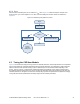
4.4.3.3 Modulator Capacitor Pin
This parameter selects the pin to which the 2.2 nF/X7R/voltage rating more than 5 V C
MOD
Note An external 2.2-nF capacitor is mandatory for the SmartSense to work correctly.
capacitor is connected.
The available pins are P0[1] and P0[3].
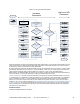
4.4.4 Scan Time of a CapSense Sensor
To maintain the consistent finger response sensitivity over a wide range of parasitic capacitance, the SmartSense
User Module automatically determines the hardware parameters of the user module. As a result of this, sensor scan
time does not remain constant. For a design in mass production, it could vary based on the parasitic capacitance
variation of the PCB.
The total scan time of a sensor is decided by four factors. They are parasitic capacitance of sensor, IMO frequency,
CPU operating frequency, and sensitivity level of the SmartSense User Module.
Scan time of a sensor can be found using Equation 12 and the following tables.
=
(
)
+ ()
Equation 12
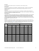
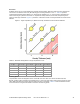
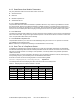
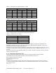
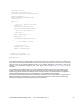
The following tables show the sampling time value with various IMO and sensitivity levels.
Table 4-4. Sampling Time for a Sensor with IMO = 24 MHz
Sensitivity = 0.2 pF Sensitivity = 0.3 pF Sensitivity = 0.4 pF
C
P
ST (µs) (pF) C
P
ST (µs) (pF) C
P
ST (µs) (pF)
8 to 10 340 8 to 17 340 8 to 10 170
10 to 23 680 17 to 35 680 10 to 23 340
23 to 41 1360 35 to 41 1360 23 to 41 680
41 to 45 2730 41 to 45 2730 41 to 45 1360