
Datasheet
CY8C20xx6A/H CapSense Design Guide Doc. No. 001-65973 Rev. *A 40
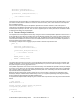
SmartSense_Start();
SmartSense_ScanAllSensors();
SmartSense_SetDefaultFingerThresholds() ;
Timer16_EnableInt();
Timer16_SetPeriod (TIMEOUT_10MS) ;
Timer16_Start();
while( 1 )
{
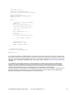
/* Scan all 3 sensors and update
Baseline */
SmartSense_ScanAllSensors();
SmartSense_UpdateAllBaselines();
/* Wait till timer expires or
sleep here */
while (bTimerTicks != 1) ;
bTimerTicks = 0 ;
if(CSDAUTO_bIsAnySensorActive() )
{
//1 ms firmware routines
}
// Toggle Port_0[1]
PRT0DR_Shadow ^= 0x01 ;
PRT0DR = PRT0DR_Shadow ;
}
}
// Timer16 ISR program
void myTimer_ISR_Handler(void)
{
bTimerTicks++;
}
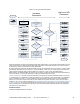
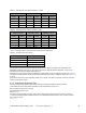
In the previous example, the program waits for the Timer to expire even if the sensor scanning is complete. The
period of the Timer should be chosen based on the worst case main loop execution time. This is the sum of the worst
case scan times of the individual CapSense sensors. If the parasitic capacitance of the sensor is close to the
boundary of the SmartSense capacitance bank, chose higher scan time (using Table 4-5 on page 38) for the
calculation.
The SmartSense User Module enables you to easily implement the capacitive touch sensing user interface into a
system. It removes the difficulties of the tuning process and also helps to increase the yield in production against
manufacturing process variations of the PCB, and other variations. Therefore, the preferred option is to migrate the
existing CSD-based CapSense designs to SmartSense and to use SmartSense for new designs.
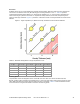
The main loop execution time and scan time of SmartSense vary based on the process variations. Though it does not
affect the performance of CapSense in any way, the firmware developer should consider this when implementing
CapSense PLUS applications with SmartSense Auto-Tuning technology.