
User guide


Getting Started with CapSense
®
Document No. 001-64846 Rev. *I 37
3.3 Electromagnetic Compatibility (EMC) Considerations
EMC is related to the generation, transmission, and reception of electromagnetic energy that can upset the working of
an electronic system. The source (emitter) produces the emission and a transfer or coupling path transfers the
emission energy to a receptor, where it is processed, resulting in either desired or undesired behavior. Many
electronic devices are required to comply with specific limits for emitted energy and susceptibility to external upsets.
Several regulatory bodies worldwide set regional regulations to help ensure that electronic devices do not interfere
with each other. These regulations helps to prevent your computer from interfering with your television, or worse, a
hospital X-ray machine or ventilator, or corrupting the operation of a critical medical monitor.
CMOS analog and digital circuits have very high input impedance. As a result, they are sensitive to external electric
fields. Take adequate precautions to ensure their proper operation in the presence of radiated and conducted noise.
3.3.1 Radiated Interference
Radiated electrical energy can influence system measurements and potentially influence the operation of the
CapSense processor core. The interference enters the CapSense chip at the PCB level, through the sensor traces,
and through other digital and analog inputs.
The following sections discuss layout guidelines to minimize the effects of RF interference.
3.3.1.1 Ground Plane
In general, providing a ground plane on the PCB helps to reduce the RF noise picked up by the CapSense controller.
3.3.1.2 Series Resistor
Every CapSense controller pin has some parasitic capacitance, C
P
, associated with it. Adding an external resistor
forms a low-pass RC filter that can dampen RF noise amplitude.
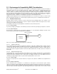
Figure 3-5. RC Filter
CapSense
Controller
CapSense
Sensor
External series
resistor
Pins
Capacitance
Place series resistors within 10 mm of the CapSense controller pins.
3.3.1.2.1 CapSense Input Lines
The recommended series resistance for CapSense input lines is 560 ohms. Adding resistance changes the time
constant of the switched-capacitor circuit that converts C
P
into an equivalent resistor. If the series resistance value is
set larger than 560 ohms, the slower time constant of the switching circuit limits the amount of charge that can
transfer. This lowers the signal level, which in turn lowers SNR. Smaller values are better, but are less effective at
blocking RF.
3.3.1.2.2 Digital Communication Lines
Communication lines, such as I
2
C and SPI, also benefit from series resistance and 330 ohms is recommended for
communication lines. Communication lines have long traces that act as antennae such as the CapSense traces. If
more than 330 ohms is placed in series on these lines, the voltage levels fall out of spec with the worst case
combination of supply voltages between systems and the input impedance of the receiver.
3.3.1.3 Trace Length
Long traces can pick up more noise than short traces. Long traces also add to C
P
. Minimize trace length whenever
possible.
3.3.1.4 Current Loop Area
Another important layout consideration is to minimize the return path for current. General system emission
suppression techniques include adding a decoupling capacitor network and reducing current loops. The current loops
create issues for both emission and immunity. A proper ground plane scheme can help reduce the path length. To
reduce the impact of parasitic capacitance, give hatched ground instead of solid fill near the sensors or traces. A solid