CDL-165ETHG ETHERNET/USB to HDMI/VGA Display Converter Operation Manual
DISCLAIMERS The information in this manual has been carefully checked and is believed to be accurate. Cypress Technology assumes no responsibility for any infringements of patents or other rights of third parties which may result from its use. Cypress Technology assumes no responsibility for any inaccuracies that may be contained in this document. Cypress also makes no commitment to update or to keep current the information contained in this document.
SAFETY PRECAUTIONS Please read all instructions before attempting to unpack, install or operate this equipment and before connecting the power supply. Please keep the following in mind as you unpack and install this equipment: • Always follow basic safety precautions to reduce the risk of fire, electrical shock and injury to persons. • To prevent fire or shock hazard, do not expose the unit to rain, moisture or install this product near water. • Never spill liquid of any kind on or into this product.
CONTENTS 1. Introduction �������������������������������������������� 1 2. Applications ������������������������������������������� 1 3. Package Contents �������������������������������� 1 4. System Requirements ���������������������������� 1 5. Features �������������������������������������������������� 2 6. Operation Controls and Functions ������� 3 6.1 Front Panel ����������������������������������������3 6.2 Rear Panel �����������������������������������������4 7.
1. INTRODUCTION The device that can send audio/video signals from a Notebook/PC over a local area network through regular Ethernet cables to a TV which can be used as the primary display. When a keyboard and mouse are plugged in, the device will lets you to edit word processing documents and play your music/movies on a TV.
whereas connection via USB supports Mac OS X (v10.4.11 and v10.5.6) • USB Port Extension: -- An available USB 2.0 port with USB to mini-USB cable • Network Extension: -- An available Ethernet port at home or a commercial network with RJ-45 cable 5.
6. OPERATION CONTROLS AND FUNCTIONS 6.1 Front Panel DC 5V 1 LAN USB USB IN INPUT LAN IN USB PORT 2 3 4 5 1 DC 5V Plug the 5V DC power supply into the unit and connect the adaptor included in the package to an AC wall outlet. 2 INPUT LAN/USB Switch This switch allows users to choose the input source signal from ethernet or USB. 3 LAN IN This slot is to connect with a CAT5e/6 cable to your network system or ethernet hub.
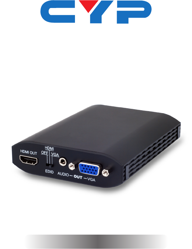
6.2 Rear Panel HDMI OUT HDMI OFF VGA 1 EDID AUDIO 2 3 OUT VGA 4 1 HDMI OUT Connect to the HDMI TV/display with HDMI cable for video and audio output. 2 EDID Control Switch The default setting for this switch is on HDMI, leave the switch here as long as the connected display is compatible. When the switch is set to 'OFF' this will allow use of the built-in EDID (the input source device must be re-powered/restarted in order for this to function).
7. SOFTWARE INSTALLATION The following sections list the procedures to follow when installing the USB to HDMI and USB device drivers. Insert the provided CD into your CD-ROM drive, then begin the USB Install Disc and follow the below steps to install the driver. 7.1 Install DispalyLink Software Insert the CD driver included in the package and double click on the DisplayLink icon to execute the setup. 7.
When both the DisplayLink and USB Server drivers have been installed the USB Server’s icon should appear on the desktop and in the system tray.
7.3 Using USB Server Double click on the 'Launch USB Server' icon from the desktop or from the icon in the system tray and the USB Server window will appear on the desktop. Connect both the PC/Laptop and the unit with a RJ-45 patch cable. Click on Search ensuring that you have set the INPUT switch on the device to LAN. Once the connection is done click on Connect Device next to the Search for both Display and Media. When the connection is done the Status will change to 'Locally Connected'.
7.4 IP Property Setting When connecting PC/Laptop directly to the device or when the network has no DHCP server a special IP setting is required. Please follow the procedure below to make the correct setting. Click Control Panel from the Windows Start Menu.
Click on the Network and Internet Connection and select Network Connections.
Double click on the Local Area Connection Double click on the Internet Protocol (TCP/IP) Click on “Use the follow IP address” and set the IP address and Subnet mask. The IP address setting should remain at 169.254.10.X (X can be 0~9&11~255) and Subnet mask can remain as 255.255.0.0 appear with “” mark. When disconnecting click on “Disconnect Device”.
8. USING DISPLAYLINK MANAGER 8.1 Using DisplayLink Manager After the driver is installed, a utility (DisplayLink Manager) will automatically appear in the system tray. The utility allows you to quickly change the settings and resolution for DisplayLink Manager. Right click on the icon will bring out the context menu. Screen Resolution Select the screen resolution (available only in extended mode).
Color Quality Select the screen color quality (available only in extended mode). Screen Rotation Rotate the screen on the additional monitor by 90, 180 or 270 degrees.
Extend to Reposition the extended screen to the top, bottom, left or right of the primary display. Extend Set the DisplayLink Manager to Extended mode.
Set as Main Monitor Set the monitor to be the main monitor. Notebook Monitor off Set the PC/notebook's monitor off.
Mirror Set the DisplayLink Manager to Mirror mode. You can see the same desktop image on the additional monitor. Off Disable the DisplayLink Manager on the system.
Advanced Opening the Display Properties will allow you to adjust the resolution, color quality, position and refresh rate. 8.2 Using More DisplayLink Manager You don’t have to install a new driver as long as you have completed the above installation process in advance. It will automatically define the ID of the new Display Link Manager and will list everything in the Display properties or the display manager menu.
9. UNINSTALL THE DEVICE DRIVER Follow the steps below to uninstall the Multi View driver. Step 1: Open the Control Panel: Start → Control Panel → Add or Remove Programs. Step 2: Select DisplayLink Core Software and click Remove. Step 3: Click Yes to confirm the removal.
Step 4: Click Yes to restart your computer. Then select DisplayLink Graphics and click Remove. Finally, select USB Server and click Remove.
10.
11. TROUBLESHOOTING Situation Check Point The device driver has been installed, but the DisplayLink Manager is not working Make sure that the computer has been restarted after the driver installation. Check all the connectors are plugged in correctly. Make sure the USB port that you are using is USB 2.0. compliant Check the additional monitor is connected correctly and the power is on.
12. SPECIFICATIONS Video Resolution Up to 1600×1200 /1920×1080 (wide) Video Input 1×Ethernet RJ-45, 1×USB 2.0 Network Protocol TCP/IP Video Output Ports 1×HDMI, 1×D-Sub 15pin VGA Extender Ports 2×USB Hubs (A type) Audio Output 1Vp-p 47 KΩ 3.5 mm Phone jack OS Support Windows XP SP2, Vista and 7 Power Supply 5 V DC/2.
13.
CYPRESS TECHNOLOGY CO., LTD Home page: http://www.cypress.com.