CY8CKIT-042 PSoC® 4 Pioneer Kit Guide Doc. # 001-86371 Rev. *D Cypress Semiconductor 198 Champion Court San Jose, CA 95134-1709 Phone (USA): 800.858.1810 Phone (Intnl): +1.408.943.2600 http://www.cypress.
Copyrights Copyrights © Cypress Semiconductor Corporation, 2013. The information contained herein is subject to change without notice. Cypress Semiconductor Corporation assumes no responsibility for the use of any circuitry other than circuitry embodied in a Cypress product. Nor does it convey or imply any license under patent or other rights.
Contents Safety Information 1. Introduction 1.1 1.2 1.3 1.4 1.5 1.6 1.7 3.3 3.4 3.5 17 Pioneer Kit USB Connection......................................................................................18 Programming and Debugging PSoC 4 ......................................................................19 3.2.1 Using the Onboard PSoC 5LP Programmer and Debugger ..........................19 3.2.2 Using CY8CKIT-002 MiniProg3 Programmer and Debugger.........................21 USB-UART Bridge .............
Contents 5. Code Examples 5.1 5.2 5.3 5.4 6. Advanced Topics 6.1 6.2 6.3 6.4 4 63 Using PSoC 5LP as USB-UART Bridge .................................................................... 63 Using PSoC 5LP as USB-I2C Bridge ........................................................................ 76 Developing Applications for PSoC 5LP ..................................................................... 84 6.3.1 Building a Bootloadable Project for PSoC 5LP .............................................
Safety Information Regulatory Compliance The CY8CKIT-042 PSoC® 4 Pioneer Kit is intended for use as a development platform for hardware or software in a laboratory environment. The board is an open system design, which does not include a shielded enclosure. Due to this reason, the board may cause interference to other electrical or electronic devices in close proximity. In a domestic environment, this product may cause radio interference.
Safety Information General Safety Instructions ESD Protection ESD can damage boards and associated components. Cypress recommends that the user perform procedures only at an ESD workstation. If an ESD workstation is not available, use appropriate ESD protection by wearing an antistatic wrist strap attached to the chassis ground (any unpainted metal surface) on the board when handling parts. Handling Boards CY8CKIT-042 boards are sensitive to ESD. Hold the board only by its edges.
1. Introduction Thank you for your interest in the PSoC® 4 Pioneer Kit. The kit is designed as an easy-to-use and inexpensive development kit, showcasing the unique flexibility of the PSoC 4 architecture. Designed for flexibility, this kit offers footprint-compatibility with several third-party Arduino™ shields. This kit has a provision to populate an extra header to support Digilent® Pmod™ peripheral modules.
Introduction Figure 1-1. Kit Contents Inspect the contents of the kit; if you find any part missing, contact your nearest Cypress sales office for help: www.cypress.com/go/support. 8 CY8CKIT-042 PSoC 4 Pioneer Kit Guide, Doc. # 001-86371 Rev.
Introduction 1.2 PSoC Creator™ PSoC Creator is a state-of-the-art, easy-to-use integrated design environment (IDE). It introduces revolutionary hardware and software co-design, powered by a library of pre-verified and precharacterized PSoC Components™.
Introduction 1.6 Document Revision History Table 1-1. Revision History Revision 1.7 Issue Date Origin of Change Description of Change ** 04/23/2013 ANCY Initial version of kit guide. *A 04/25/2013 ANCY Minor changes across the guide. *B 05/23/2013 RKAD Updated Figure 1-1 and minor changes across the guide. Added PSoC 5LP Factory Program Restore Instructions on page 93. *C 08/23/2013 SASH Updated Figure 5-2 and Figure 5-3. Minor changes across the guide.
2. 2.1 Software Installation Install Kit Software Follow these steps to install the PSoC 4 Pioneer Kit software: 1. Download and install the PSoC 4 Pioneer Kit software from www.cypress.com/go/CY8CKIT-042. 2. Select the folder to install the CY8CKIT-042 related files. Choose the directory and click Next. Figure 2-1. Installation Folder CY8CKIT-042 PSoC 4 Pioneer Kit Guide, Doc. # 001-86371 Rev.
Software Installation 3. Select the installation type and click Next. Figure 2-2. Installation Type Options After the installation is complete, the kit contents are available at the following location: :\CY8CKIT-042 PSoC 4 Pioneer Kit\ Note For Windows 7 users, the installed files and the folder are read-only. To change the property, right-click the folder and select Properties > Attributes; disable the Read-only radio button. Click Apply and OK to close the window. 2.
Software Installation 2.4 Uninstall Software The software can be uninstalled using one of the following methods: 2.5 ■ Go to Start > All Programs > Cypress > Cypress Update Manager > Cypress Update Manager; select the Uninstall button. ■ Go to Start > Control Panel > Programs and Features; select the Uninstall/Change button. Develop Code Fast and Easy with Code Examples PSoC Creator provides several example projects that make code development fast and easy.
Software Installation Figure 2-4. Starter Designs In addition to the example projects and starter designs that are available within PSoC Creator, Cypress continuously strives to provide the best support. Click here to view a growing list of application notes for PSoC 3, PSoC 4, and PSoC 5LP. 14 CY8CKIT-042 PSoC 4 Pioneer Kit Guide, Doc. # 001-86371 Rev.
Software Installation 2.6 Open an Example Project in PSoC Creator 1. Launch PSoC Creator from the Start menu. Figure 2-5. PSoC Creator Start Page 2. Open the example project from the Start Page by clicking present below the Examples and Kits > Kits > CY8CKIT-042. Figure 2-6. Open Example Project CY8CKIT-042 PSoC 4 Pioneer Kit Guide, Doc. # 001-86371 Rev.
Software Installation 3. The example project opens and displays the project files in the Workspace Explorer. Subsequent sections of this user guide describe how to build, program, and understand the example projects supported in this kit. Figure 2-7. Workspace Explorer 16 CY8CKIT-042 PSoC 4 Pioneer Kit Guide, Doc. # 001-86371 Rev.
3. Kit Operation The PSoC 4 Pioneer Kit can be used to develop applications using the PSoC 4 family of devices and the Arduino shields and Digilent Pmod daughter cards. Figure 3-1 is an image of the PSoC 4 Pioneer board with a markup of the onboard components. Figure 3-1.
Kit Operation 3.1 Pioneer Kit USB Connection The PSoC 4 Pioneer Kit connects to the PC over a USB interface. The kit enumerates as a composite device and three separate devices appear under the Device Manager window in the Windows operating system. Table 3-1. PSoC 4 Pioneer Kit in Device Manager after Enumeration Port Description USB Input Device USB-I2C bridge KitProg Programmer and debugger KitProg USB-UART USB-UART bridge will appear as a COM# port Figure 3-2.
Kit Operation 3.2 Programming and Debugging PSoC 4 The kit allows programming and debugging of the PSoC 4 device in two modes: 3.2.1 ■ Using the onboard PSoC 5LP programmer and debugger ■ Using a CY8CKIT-002 MiniProg3 programmer and debugger Using the Onboard PSoC 5LP Programmer and Debugger The default programming interface for the kit is a USB-based, onboard programming interface. Before trying to program the device, PSoC Creator and PSoC Programmer must be installed.
Kit Operation 3. The Pioneer Kit’s onboard programmer will enumerate on the PC and in the software tools as KitProg. Load an example project in PSoC Creator (such as the project described in Install Software on page 12) and initiate the build by clicking Build > Build Project or [Shift]+[F6]. Figure 3-6. Build Project in PSoC Creator 4. After the project is built without errors and warnings, select Debug > Program or [Ctrl]+[F5] to program the device. Figure 3-7.
Kit Operation 3.2.2 Using CY8CKIT-002 MiniProg3 Programmer and Debugger The PSoC 4 on the Pioneer Kit can also be programmed using a MiniProg3 (CY8CKIT-002). To use MiniProg3 for programming, use the J6 connector on the board, as shown in Figure 3-8. With MiniProg3, programming is similar to the onboard programmer; however, the setup enumerates as a MiniProg3. Only the RESET programming mode is available. The board can also be powered from the MiniProg3. To do this, select Tool > Options.
Kit Operation Figure 3-9. MiniProg3 Configuration 3.3 USB-UART Bridge The onboard PSoC 5LP can also act as a USB-UART bridge to transfer and receive data from the PSoC 4 device to the PC via the COM terminal software. When the USB mini-B cable is connected to J10 of the PSoC 4 Pioneer Kit, a device named KitProg USBUART is available under Ports (COM & LPT) in the device manager. For more details about the USB-UART functionality, see Using PSoC 5LP as USB-UART Bridge on page 63.
Kit Operation Figure 3-10. Example RX and TX Line Connection of PSoC 5LP and PSoC 4 Table 3-2 lists the specifications supported by the USB-UART bridge. Table 3-2. Specifications Supported by USB-UART Bridge Parameter Baud Rate Supported Values 1200, 2400, 4800, 9600, 19200, 38400, 57600, and 115200 Data Bits 8 Parity None Stop Bits 1 Flow Control None File transfer protocols supported Xmodem, 1K Xmodem, Ymodem, Kermit, and Zmodem (only speeds greater than 2400 baud).
Kit Operation 3.4 USB-I2C Bridge The PSoC 5LP also functions as a USB-I2C bridge. The PSoC 4 communicates with the PSoC 5LP using an I2C interface and the PSoC 5LP transfers the data over the USB to the USB-I2C software utility on the PC, called the Bridge Control Panel (BCP). The BCP is available as part of the PSoC Programmer installation. This software can be used to send and receive USB-I2C data from the PSoC 5LP.
Kit Operation Figure 3-12. KitProg USB-I2C Connected in Bridge Control Panel USB-I2C is implemented using the USB and I2C components of PSoC 5LP. The SCL (P12_0) and SDA (P12_1) lines from the PSoC 5LP are connected to SCL (P3_0) and SDA (P3_1) lines of the PSoC 4 I2C. The USB-I2C bridge currently supports I2C speed of 50 kHz, 100 kHz, 400 kHz, and 1 MHz. Refer to Using PSoC 5LP as USB-I2C Bridge on page 76 for building a project, which uses USB-I2C Bridge functionality. 3.
Kit Operation Click OK to close the window. On closing the warning window, the Action and Results window displays “Please navigate to the Utilities tab and click the Upgrade Firmware button”. Figure 3-14. Upgrade Firmware Message in PSoC Programmer Click the Utilities tab and click the Upgrade Firmware button. On successful upgrade, the Action and Results window displays the firmware update message with the KitProg version. Figure 3-15.
4. 4.1 Hardware Board Details The PSoC 4 Pioneer Kit consists of the following blocks: ■ PSoC 4 ■ PSoC 5LP ■ Power supply system ■ Programming interfaces (J6, J7 - unpopulated, J10) ■ Arduino compatible headers (J1, J2, J3, J4, and J12 - unpopulated) ■ Digilent Pmod compatible header (J5 - unpopulated) ■ PSoC 5LP GPIO header (J8) ■ CapSense slider ■ Pioneer board LEDs ■ Push buttons (Reset and User buttons) Figure 4-1.
Hardware Figure 4-2. PSoC 4 Pioneer Kit Pin Mapping P12_6 P3_4 P5_VDD P3_6 P0_0 GND PSoC 5LP I/O Header (J8) P3_0 P3_7 P12_7 P0_1 P1_2 P3_5 VCC/P4_VDD GND/GND SCK/P0_6 MISO/P3_1 MOSI/P3_0 Digilent Pmod Compatible I/O Header (J5) P4_0 P4_1 SS/P3_5 P1_7/AREF GND/GND NC Arduino Compatible I/O Header (J3) OREF/P4_VDD RESET/RESET 3.3V/V3.
Hardware 4.2 Theory of Operation This section provides the block-level description of the PSoC 4 Pioneer Kit. Figure 4-3. Block Diagram The PSoC 4 is a new generation of programmable system-on-chip devices from Cypress for embedded applications. It combines programmable analog, programmable digital logic, programmable I/O, and a high-performance ARM Cortex-M0 subsystem. With the PSoC 4, you can create the combination of peripherals required to meet the application specifications.
Hardware 4.3 Functional Description 4.3.1 PSoC 4 This kit uses the PSoC 4200 family device. PSoC 4200 devices are a combination of a microcontroller with programmable logic, high-performance analog-to-digital conversion, two opamps with comparator mode, and commonly used fixed-function peripherals. For more information, refer to the PSoC 4 web page and the PSoC 4200 family datasheet.
Hardware Applications Programming Interface (API) component for all fixed-function and programmable peripherals Industry-standard tool compatibility ❐ After schematic entry, development can be done with ARM-based industry-standard development tools ❐ ■ For more information see the CY8C42 family datasheet. 4.3.2 PSoC 5LP An onboard PSoC 5LP is used to program and debug PSoC 4. The PSoC 5LP connects to the USB port of the PC through a USB Mini B connector and to the SWD interface of the PSoC 4 device.
Hardware Four 16-bit configurable timers, counters, and PWM blocks ❐ 67-MHz, 24-bit fixed point digital filter block (DFB) to implement finite impulse response (FIR) and infinite impulse response (IIR) filters ❐ Library of standard peripherals a.8-, 16-, 24-, and 32-bit timers, counters, and PWMs b.Serial peripheral interface (SPI), universal asynchronous transmitter receiver (UART), and I2C c.Many others available in catalog ❐ Library of advanced peripherals a.Cyclic redundancy check (CRC) b.
Hardware 4.3.3 Power Supply System The power supply system on this board is versatile, allowing the input supply to come from the following sources: ■ 5-V power from onboard USB programming header J10 ■ 5-V to 12-V power from Arduino shield using J1_01 header ■ VTARG - power from the onboard SWD programming using J6 or J7 ■ VIN - J11 The PSoC 4 and PSoC 5LP are powered with either a 3.3 V or 5 V source. The selection between 3.3 V and 5 V is made through the J9 jumper. The board can supply 3.
Hardware 4.3.3.1 Protection Circuit The power supply rail has reverse-voltage, over-voltage, short circuits, and excess current protection features, as seen in Figure 4-4. 4.3.3.2 ■ The Schottky diode (D1) ensures power cannot be supplied to the 5-V domain of the board from the I/O header. ■ The series protection diode (D2) ensures VIN (power supply from the I/O header) does not back power the USB. ■ The Schottky diode (D3) ensures 3.3 V from I/O header does not back power the LDO.
Hardware Figure 4-6. PSoC 4 Current Measurement when Powered Separately VOLTAGE SOURCE ■ When the PSoC 4 is powered separately and the PSoC 5LP is not powered, make these changes to avoid leakage while measuring current: ❐ Remove the zero-ohm resistors R24 and R25. Removing these resistors will affect the USBI2C functionality. ❐ Remove R11, R15, and R16, which are meant for programming the PSoC 4. Removing these resistors disables the PSoC 5LP capability for programming.
Hardware 4.3.5 Arduino Compatible Headers (J1, J2, J3, J4, and J12 - unpopulated) This kit has five Arduino compatible headers; J1, J2, J3, J4 and J12. You can develop applications based on the Arduino shield’s hardware. Figure 4-8. Arduino Header The J1 header contains I/O pins for reset, internal reference voltage (IOREF), and power supply line. The J2 header is an analog port. It contains I/O pins for SAR ADC, comparator, and opamp. The J3 header is primarily a digital port.
Hardware Figure 4-9. Arduino Compatible Headers Arduino Compatible I/O Header (J4) Arduino Compatible I/O Header (J3) Arduino Compatible ICSP I/O Header (J12) Arduino Compatible I/O Header (J2) Arduino Compatible I/O Header (J1) P4_VDD 0603 R8 2.2K I2C Pull up R9 2.2K Resistors 0603 TVS4 18V 350W BI J3 VBUS VIN P4_0 P4_1 J1 1 2 3 4 5 6 7 8 D4 SOD123 V3.
Hardware 4.3.5.2 Functionality of Unpopulated Header J12 The J12 header is a 2×3 header that supports Arduino shields. This header is used on a small subset of shields and is unpopulated on the PSoC 4 Pioneer Kit. Note that the J12 header only functions in 5.0 V mode. To ensure proper shield functionality, ensure the power jumper is connected in 5.0 V mode. 4.3.6 Digilent Pmod Compatible Header (J5 - unpopulated) This port supports Digilent Pmod peripheral modules.
Hardware Figure 4-11. Digilent Pmod Interface J5 P4_VDD P3_5 P3_0 P3_1 P0_6 1 2 3 4 5 6 6X1 CONN FEMALE NO LOAD J5 Digilent PMOD Cards Compatible Headers See A.2 Pin Assignment Table on page 104 for details on the pin descriptions for the J5 header. 4.3.7 PSoC 5LP GPIO Header (J8) A limited set of PSoC 5LP pins are brought to this header. Refer to 6.3 Developing Applications for PSoC 5LP on page 84 for details on how to develop custom applications. See A.
Hardware 4.3.8 CapSense Slider The kit has a five-segment linear capacitive touch slider on the board, which is connected to pins P1[1] to P1[5] of the PSoC 4 device. The modulation capacitor (Cmod) is connected to pin P4[2] and an optional bleeder resistor (R1) can be connected across the Cmod. This board supports CapSense designs that enable waterproofing. The waterproofing design uses a concept called shield, which is a conductor placed around the sensors.
Hardware 4.3.9 Pioneer Board LEDs The PSoC 4 Pioneer board has three LEDs. A green LED (D10) indicates the status of the programmer. See A.5 Error in Firmware/Status Indication in Status LED for a detailed list of LED indications. An amber LED (D3) indicates status of power supplied to the board. The kit also has a general-purpose tricolor LED (D9) for user applications that connect to specific PSoC 4 pins. Figure 4-15 shows the indication of all these LEDs on the board.
Hardware 4.3.10 Push Buttons The kit contains a Reset push button and a User push button, as shown in Figure 4-18. The Reset button is connected to the XRES pin of PSoC 4 and is used to reset the onboard PSoC 4 device. The User button is connected to P0[7] of PSoC 4 device. Both the push buttons connect to ground on activation (active low). Figure 4-18. Push Buttons SW1 /XRES 1 2 EVQ-PE105K RESET SW2 P0_7 1 2 EVQ-PE105K USER BUTTON 42 CY8CKIT-042 PSoC 4 Pioneer Kit Guide, Doc. # 001-86371 Rev.
5. Code Examples The code examples described in this chapter introduce the functionality of the PSoC 4 device and the onboard components. To access the examples, download the CD ISO image or setup files from the kit web page. The code examples will be available in the firmware folder in the install location. Follow these steps to open and program code examples: 1. Launch PSoC Creator from the Start menu. 2. Open the code example by clicking
Code Examples 3. Build the code example by clicking Build > Build to generate the hex file. Figure 5-2. Build Project from PSoC Creator 4. To program, connect the board to a computer using the USB cable connected to port J10, as described in section 3.1 Pioneer Kit USB Connection. The board is detected as KitProg. 5. Click Debug > Program from PSoC Creator. Figure 5-3. Program Device from PSoC Creator 6. If the device is not yet acquired, PSoC Creator will open the programming window.
Code Examples 7. After the device is acquired, it is shown in a tree structure below the KitProg. Now, click the Connect button. Figure 5-5. Connect Device from PSoC Creator 8. Click OK to exit the window and start programming. Figure 5-6. Program Device from PSoC Creator CY8CKIT-042 PSoC 4 Pioneer Kit Guide, Doc. # 001-86371 Rev.
Code Examples 5.1 Project: Blinking LED 5.1.1 Project Description This example uses a pulse-width modulator (PWM) to illuminate the RGB LED. The PWM output is connected to pin P0_3 (blue) of the RGB LED. The frequency of blinking is set to 1 Hz with a duty cycle of 50 percent. The blinking frequency and duty cycle can be varied by varying the period and compare value respectively. Note: The PSoC 4 Pioneer Kit is factory-programmed with this example. Figure 5-7.
Code Examples Figure 5-8. Pin Selection for Blinking LED Project 5.1.3 Flow Chart Figure 5-7 shows the flow chart of code implemented in main.c. Figure 5-9. Blinking LED Project Flow Chart 5.1.4 Verify Output Build and program the code example onto the device. Observe the frequency and duty cycle of the blinking LED. Change the period and compare value in the PWM component, as shown in Figure 5-10. Rebuild and reprogram the device to vary the frequency and duty cycle.
Code Examples Figure 5-10. PWM Component Configuration Window 48 CY8CKIT-042 PSoC 4 Pioneer Kit Guide, Doc. # 001-86371 Rev.
Code Examples 5.2 Project: PWM 5.2.1 Project Description This code example demonstrates the use of the PWM component. The project uses three PWM outputs to set the color of RGB LED on the Pioneer Kit. The LED cycles through seven colors – violet > indigo > blue > green > yellow > orange > red (VIBGYOR). Each color is maintained for a duration of one second. The different colors are achieved by changing the pulse width of the PWMs. Figure 5-11. PSoC Creator Schematic Design of PWM Project 5.2.
Code Examples Figure 5-12. Pin Selection for PWM Project 5.2.3 Flow Chart Figure 5-13 shows the flow chart of code implemented in main.c. Figure 5-13. PWM Project Flow Chart 50 CY8CKIT-042 PSoC 4 Pioneer Kit Guide, Doc. # 001-86371 Rev.
Code Examples 5.2.4 Verify Output Build and program the code example, and reset the device. Observe the RGB LED cycles through the color pattern. 5.3 Project: Deep Sleep 5.3.1 Project Description This project demonstrates the low-power functionality of the PSoC 4. The LED is turned on for one second to indicate Active mode; then, the device enters Deep-Sleep mode. When switch SW2 is pressed, the device wakes up and the LED is turned on for one second and then goes back into Deep-Sleep mode.
Code Examples Figure 5-15. Pin Selection for Deep-Sleep Project 5.3.3 Flow Chart Figure 5-16 shows the flow chart of code implemented in main.c. Figure 5-16. Deep-Sleep Project Flow Chart Start Turn LED on for one second Enter DeepSleep mode Interrupt on SW2 press Clear the interrupt 52 CY8CKIT-042 PSoC 4 Pioneer Kit Guide, Doc. # 001-86371 Rev.
Code Examples 5.3.4 Verify Output Build and program the code example, and reset the device. LED is on for one second and turns off, which indicates that the device has entered Deep-Sleep mode. Press SW2 switch to wake up the device from Deep-Sleep mode and enter Active mode. The device goes back to sleep after one second. Note: When the device is in Deep-Sleep mode, the programmer must reacquire the device before programming can start. 5.
Code Examples 5.4.1.2 Hardware Connections No specific hardware connections are required for this project because all connections are hardwired on the board. Open CapSense.cydwr in the Workspace Explorer and select the suitable pins. Table 5-4.
Code Examples 5.4.1.3 Flow Chart Figure 5-19 shows the flow chart of code implemented in main.c. Figure 5-19. CapSense Project Flow Chart 5.4.1.4 Verify Output The brightness of the green and red LEDs are varied based on the position of the user’s finger on the CapSense slider. When the finger is on segment 5 (P1[5]) of the slider, the green LED is brighter than the red LED; when the finger is on segment 1 (P1[1]) of the slider, the red LED is brighter than the green LED. 5.4.
Code Examples In this example, the brightness of the green and red LEDs are varied, based on the position of the user's finger on the CapSense slider. See Figure 5-17 for the project schematic. 5.4.2.2 Hardware Connections No specific hardware connections are required for this project because all connections are hardwired on the board. Open CapSense.cydwr in the Workspace Explorer and select the suitable pins. See Table 5-4 and Figure 5-18 for the CapSense project pin connections. 5.4.2.
Code Examples 5.4.2.4 Launching Tuner GUI The Tuner GUI from PSoC Creator should be up and running for the code example to work. To launch the GUI follow these steps: 1. Go to the project's TopDesign.cysch file. Figure 5-21. Top Design File 2. To open the tuner, right-click on the CapSense_CSD component in PSoC Creator and click Launch Tuner. Figure 5-22. Launch Tuner 3. The Tuner GUI opens. Click Configuration to open the configuration window. CY8CKIT-042 PSoC 4 Pioneer Kit Guide, Doc.
Code Examples Figure 5-23. Tuner GUI 4. Set the I2C communication parameters, as shown in the following figure. Figure 5-24. I2C Communication 58 CY8CKIT-042 PSoC 4 Pioneer Kit Guide, Doc. # 001-86371 Rev.
Code Examples 5. Click OK to apply the settings. 5.4.2.5 Verify Output 1. To start the scanning and communication process, click Start. Figure 5-25. Start Communication CY8CKIT-042 PSoC 4 Pioneer Kit Guide, Doc. # 001-86371 Rev.
Code Examples 2. Select a sensor in the Tuning tab. A red outline is seen on the selected sensor. Different CapSense parameters are shown on the bottom-right. You cannot edit the settings because autotuning is used in this project; auto-tuning automatically sets all the parameters. Touch the selected sensor and observe the response in the tuner window. Figure 5-26. Sensor Tuning 3.
Code Examples Figure 5-27. Sensor Parameter Graph CY8CKIT-042 PSoC 4 Pioneer Kit Guide, Doc. # 001-86371 Rev.
Code Examples 5. Touch a sensor or slider element and see the increase in raw counts. Figure 5-28. Raw Count Increase 62 CY8CKIT-042 PSoC 4 Pioneer Kit Guide, Doc. # 001-86371 Rev.
6. 6.1 Advanced Topics Using PSoC 5LP as USB-UART Bridge The PSoC 5LP serves as a USB-UART bridge, which can communicate with the COM terminal software. This section explains how to create a PSoC 4 code example to communicate with the COM terminal software. This project is available with other code examples for the PSoC 4 Pioneer Kit at the element14 web page, 100 Projects in 100 days.
Advanced Topics 2. Drag and drop a UART (SCB) component to the top design. Figure 6-2. UART Component Under Component Catalog 3. To configure the UART, double-click or right-click on the UART component and select Configure. Figure 6-3. Open UART Configuration Window 64 CY8CKIT-042 PSoC 4 Pioneer Kit Guide, Doc. # 001-86371 Rev.
Advanced Topics 4. Configure the UART as shown in the following figures. Figure 6-4. UART Configuration Window Figure 6-5. UART Basic Configuration Window CY8CKIT-042 PSoC 4 Pioneer Kit Guide, Doc. # 001-86371 Rev.
Advanced Topics Figure 6-6. UART Advanced Configuration Window 5. Select P0[4] for UART RX and P0[5] for UART TX in the Pins tab of . Figure 6-7. Pin Selection 66 CY8CKIT-042 PSoC 4 Pioneer Kit Guide, Doc. # 001-86371 Rev.
Advanced Topics 6. Place the following code in your main.c project file. The code will echo any UART data received. int main() { uint8 ch; /* Start SCB UART TX+RX operation */ UART_Start(); /* Transmit String through UART TX Line */ UART_UartPutString("CY8CKIT-042 USB-UART"); for(;;) { /* Get received character or zero if nothing has been received yet */ ch = UART_UartGetChar(); if(0u != ch) { /* Send the data through UART. This functions is blocking and waits until there is an entry into the TX FIFO.
Advanced Topics 7. Build the project by clicking Build > Build {Project Name} or [Shift] + [F6]. After the project is built without errors and warnings, program (by clicking Debug > Program) the project to PSoC 4 through the PSoC 5LP USB programmer or MiniProg3. Connect the RX line of the PSoC 4 to J8_10 and TX line of the PSoC 4 to J8_9, as shown in the following figures. Figure 6-8. UART Connection Between PSoC 4 and PSoC 5LP Figure 6-9.
Advanced Topics To communicate with the PSoC 4 from the terminal software, follow this procedure: 1. Connect USB Mini B to J10. The kit enumerates as a KitProg USB-UART and is available under the Device Manager, Ports (COM & LPT). A communication port is assigned to the KitProg USB-UART. Figure 6-10. KitProg USB-UART in Device Manager 2. Open HyperTerminal and select File > New Connection and enter a name for the new connection and click OK.
Advanced Topics Figure 6-11. Open New Connection HyperTerminal PuTTY 3. A new window opens, where the communication port can be selected. In HyperTerminal, select COMX (or the specific communication port that is assigned to KitProg USB-UART) in Connect using and click OK. In PuTTY enter the COMX in Serial line to connect to. This code example uses COM12. 70 CY8CKIT-042 PSoC 4 Pioneer Kit Guide, Doc. # 001-86371 Rev.
Advanced Topics Figure 6-12. Select Communication Port HyperTerminal PuTTY 4. In HyperTerminal, select 'Bits per second', 'Data bits', 'Parity', 'Stop bits', and 'Flow control' under Port Settings and click OK. Make sure that the settings are identical to the UART settings configured for PSoC 4. In PuTTY select 'Speed (baud)', 'Data bits', 'Stop bits', 'Parity' and 'Flow control' under Configure the serial line. Click Session and select Serial under Connection type.
Advanced Topics Serial line shows the communication port (COM12) and Speed shows the baud rate selected. Click Open to start the communication. Figure 6-13. Configure the Communication Port HyperTerminal PuTTY 72 CY8CKIT-042 PSoC 4 Pioneer Kit Guide, Doc. # 001-86371 Rev.
Advanced Topics Figure 6-14. Select Communication Type in PuTTY 5. Enable Echo typed characters locally under File > Properties > Settings > ASCII Setup, to display the typed characters on HyperTerminal. In PuTTY, enable the Force on under Terminal > Line discipline options to display the typed characters on the PuTTY. Figure 6-15. Enabling echo of typed characters in HyperTerminal CY8CKIT-042 PSoC 4 Pioneer Kit Guide, Doc. # 001-86371 Rev.
Advanced Topics Figure 6-16. Enabling echo of typed characters in PuTTY 6. The COM terminal software displays both the typed data and the looped back data from the PSoC 4 UART. Figure 6-17. Data Displayed on HyperTerminal 74 CY8CKIT-042 PSoC 4 Pioneer Kit Guide, Doc. # 001-86371 Rev.
Advanced Topics Figure 6-18. Data Displayed on PuTTY CY8CKIT-042 PSoC 4 Pioneer Kit Guide, Doc. # 001-86371 Rev.
Advanced Topics 6.2 Using PSoC 5LP as USB-I2C Bridge The PSoC 5LP serves as a USB-I2C bridge, which can be used to communicate with the USB-I2C software running on the PC. This project is available with other code examples for the PSoC 4 Pioneer Kit at the element14 web page, 100 Projects in 100 days. The following steps describe how to use the USB-I2C bridge, which can communicate between the BCP and the PSoC 4. 1. Open a new project targeting the PSoC 4 device in PSoC Creator. Figure 6-19.
Advanced Topics 2. Drag and drop an I2C component to the top design. Figure 6-20. I2C Component in Component Catalog 3. To configure the I2C component, double-click or right-click on the I2C component and select Configure. Figure 6-21. Open I2C Configuration Window CY8CKIT-042 PSoC 4 Pioneer Kit Guide, Doc. # 001-86371 Rev.
Advanced Topics 4. Configure the I2C with the following settings. Figure 6-22. I2C Configuration Tab Figure 6-23. I2C Tab 5. Select pin P3[0] for the I2C SCL and pin P3[1] for the I2C SDA in the Pins tab of . 78 CY8CKIT-042 PSoC 4 Pioneer Kit Guide, Doc. # 001-86371 Rev.
Advanced Topics Figure 6-24. Pin Selection 6. Place the following code in your main.c project file. The code will enable the PSoC 4 device to transmit and receive I2C data to and from the BCP application.
Advanced Topics if(0u != (I2C_I2CSlaveStatus() & I2C_I2C_SSTAT_WR_CMPLT)) { /* Read the number of bytes transferred */ byteCnt = I2C_I2CSlaveGetWriteBufSize(); /* Clear the write status bits*/ I2C_I2CSlaveClearWriteStatus(); /* Move the data written by the master to the read buffer so that the master can read back the data */ for(indexCntr = 0; indexCntr < byteCnt; indexCntr++) { rdBuf [indexCntr] = wrBuf[indexCntr]; /* Loop back the data to the read buffer */ } /* Clear the write buffer pointer so that th
Advanced Topics Figure 6-25. Connecting to KitProg/ in BCP 9. Open Protocol Configuration from the Tools menu and select the appropriate I2C Speed. Make sure the I2C speed is the same as the one configured in the I2C component. Click OK to close the window. Figure 6-26. Opening Protocol Configuration Window in BCP CY8CKIT-042 PSoC 4 Pioneer Kit Guide, Doc. # 001-86371 Rev.
Advanced Topics 10.From the BCP, transfer five bytes of data to the I2C device with slave address 0x08. The log shows whether the transaction was successful. A '+' indication after each byte indicates that the transaction was successful and a '–' indicates that the transaction was a failure. Figure 6-27. Entering Commands in BCP 82 CY8CKIT-042 PSoC 4 Pioneer Kit Guide, Doc. # 001-86371 Rev.
Advanced Topics Figure 6-28. NACK Indication in BCP 11. From the BCP, read five bytes of data from the I2C slave device with slave address 0x08. The log shows whether the transaction was successful. Figure 6-29. Read Data Bytes from the BCP Note: Refer Help Contents under Help in BCP or press [F1] for details of I2C commands. CY8CKIT-042 PSoC 4 Pioneer Kit Guide, Doc. # 001-86371 Rev.
Advanced Topics 6.3 Developing Applications for PSoC 5LP The PSoC 4 Pioneer Kit has an onboard PSoC 5LP whose primary function is that of a programmer and a bridge. You can build either a normal project or a bootloadable project using the PSoC 5LP. The PSoC 5LP connections in the Pioneer board are summarized in Figure 6-30. J8 is the I/O connector (see section 4.3.7 PSoC 5LP GPIO Header (J8)). The USB (J10) is connected and used as the PC interface.
Advanced Topics 1. In PSoC Creator, select New > Project > PSoC 5LP; click the expand button adjacent to Advanced and select the Device as CY8C5868LTI-LP039, as shown in Figure 6-33. Select the Application Type as Bootloadable from the drop-down list. Figure 6-32. Opening New Project in PSoC Creator CY8CKIT-042 PSoC 4 Pioneer Kit Guide, Doc. # 001-86371 Rev.
Advanced Topics Figure 6-33. Selecting Device in PSoC Creator 2. Navigate to the Schematic view and drag and drop a bootloadable component on the top design. Figure 6-34. Bootloadable Component in Component Catalog 86 CY8CKIT-042 PSoC 4 Pioneer Kit Guide, Doc. # 001-86371 Rev.
Advanced Topics Set the dependency of the Bootloadable component by selecting the Dependencies tab in the configuration window and clicking the Browse button. Select the KitProg_Bootloader.hex and KitProg_Bootloader.elf files; click Open. Figure 6-35. Configuration Window of Bootloadable Component Figure 6-36. Selecting KitProg Bootloader Hex File CY8CKIT-042 PSoC 4 Pioneer Kit Guide, Doc. # 001-86371 Rev.
Advanced Topics Figure 6-37. Selecting KitProg Bootloader Elf File 3. Develop your custom project. 4. The NVL setting of the Bootloadable project and the KitProg_Bootloader project must be the same. The KitProg_Bootloader.cydwr system settings is shown in the following figure. Figure 6-38. KitProg Bootloader System Settings 5. Build the project in PSoC Creator by selecting Build > Build Project or [Shift]+[F6]. 88 CY8CKIT-042 PSoC 4 Pioneer Kit Guide, Doc. # 001-86371 Rev.
Advanced Topics 6. To download the project on to the PSoC 5LP device, open the Bootloader Host Tool, which is available from PSoC Creator. Select Tools > Bootloader Host. Figure 6-39. Opening Bootloader Host Tool from PSoC Creator 7. In the Bootloader Host tool, click Filters and add a filter to identify the USB device. Set VID as 0x04B4, PID as 0xF13B, and click OK. Figure 6-40. Port Filters Tab in Bootloader Host Tool CY8CKIT-042 PSoC 4 Pioneer Kit Guide, Doc. # 001-86371 Rev.
Advanced Topics 8. In the Bootloader Host tool, click the Open File button to browse to the location of the bootloadable file (*.cyacd). Figure 6-41. Opening Bootloadable File from Bootloader Host Tool 9. Keep the reset switch (SW1) pressed and plug in the USB Mini-B connector. If the switch is pressed for more than 100 ms, the PSoC 5LP enters into bootloader. Press the Program button in the Bootloader Host tool to program the device.
Advanced Topics 10.If bootload is successful, the log of the tool displays "Successful"; otherwise, it displays "Failed" and a statement for the failure. Notes: 1. The PSoC 5LP pins are brought to the PSoC 5LP GPIO header (J8). These pins are selected to support high-performance analog and digital projects. See A.2 Pin Assignment Table on page 104 for pin information. 2. Take care when allocating the PSoC 5LP pins for custom applications. For example, P2[0]–P2[4] are dedicated for programming the PSoC 4.
Advanced Topics 6.3.2 Building a Normal Project for PSoC 5LP A normal project is a completely new project created for the PSoC 5LP device on the CY8CKIT-042. Here the entire flash of the PSoC 5LP is programmed, overwriting all bootloader and programming code. To recover the programmer, reprogram the PSoC 5LP device with the factory-set KitProg.hex file, which is shipped with the kit installer. The KitProg.
Advanced Topics 6. Click on the device and click Connect to program. Notes: 1. The 10-pin SWD debug and programming header (J7) is not populated. See the 'No Load Components' section of A.6 Bill of Materials (BOM) for details. 2. The PSoC 5LP pins are brought to the PSoC 5LP GPIO header (J8). These pins are selected to support high-performance analog and digital projects. See A.2 Pin Assignment Table for pin information. 3. Take care when allocating the PSoC 5LP pins for custom applications.
Advanced Topics 3. The following message appears in the PSoC Programmer results window “KitProg Bootloader device is detected”. Figure 6-44. PSoC Programmer Results Window 4. Switch to the Utilities tab in PSoC Programmer and press the Upgrade Firmware button. Unplug all other PSoC programmers (such as MiniProg3 and DVKProg) from the PC before pressing the Upgrade Firmware button. Figure 6-45. Upgrade Firmware 94 CY8CKIT-042 PSoC 4 Pioneer Kit Guide, Doc. # 001-86371 Rev.
Advanced Topics 5. After programming has completed, the following message appears: “Firmware Update Finished at
Advanced Topics 6.4.1.2 Restore PSoC 5LP Factory Program Using USB Host Tool 1. Launch the Bootloader Host tool from Start > Cypress > PSoC Creator. 2. Using the File > Open menu, load the Kit Prog.cyacd file, which is installed with the kit software. The default location for this file is: \CY8CKIT-042 PSoC 4 Pioneer Kit\\Firmware\Programmer\KitProg\KitProg.cyacd Figure 6-47. Load KitProg.cyacd File 96 CY8CKIT-042 PSoC 4 Pioneer Kit Guide, Doc. # 001-86371 Rev.
Advanced Topics 3. Configure the Pioneer Kit in Service Mode. To do this, while holding down the reset button (SW1 Reset), plug in the PSoC 4 Pioneer Kit to the computer using the included USB cable (USB A to mini-B). This puts the PSoC 5LP into service mode, which is indicated by the blinking green status LED. 4. In the Bootloader Host tool, set the filters for the USB devices with VID: 04B4 and PID: F13B. USB Human Interface Device port appears in the Ports list. Click that port to select it.
Advanced Topics Figure 6-49. Programming Finished Successfully 7. The factory program is now successfully restored on the PSoC 5LP. It can be used as the programmer/debugger for the PSoC 4 device. 6.4.2 PSoC 5LP is Programmed with a Standard Application If PSoC 5LP is programmed with a standard application, restore the factory program by using the following method. 1. Launch PSoC Programmer 3.18 or later from Start > Cypress > PSoC Programmer. 2. Use the File > Open menu to load the KitProg.
Advanced Topics 4. Ensure that MiniProg3 is the selected port in PSoC Programmer and the 10-pin connector (10p option) is selected, as shown in the following figure. If the board is not powered over USB, select the Power Cycle programming mode. Figure 6-50. Select MiniProg3 5. When ready, press the Program button (or File > Program) to program the PSoC 5LP device. 6. After programming has completed, the following message appears: “Program Finished at
Advanced Topics Figure 6-51. Program Finished 7. The factory program is now successfully restored on the PSoC 5LP. It can be used as the programmer/debugger for the PSoC 4 device. 100 CY8CKIT-042 PSoC 4 Pioneer Kit Guide, Doc. # 001-86371 Rev.
A. A.1 Appendix CY8CKIT-042 Schematics C10 1.0 uF PLACE CAPS CLOSE TO POWER PINS 0603 P4_VDD P1_7 P1_6 P1_5 P1_4 P1_3 P1_2 P1_1 P1_0 P4_VDD C2 0.1 uF VCCD C3 1.0 uF 0402 C5 1.0 uF 44 43 42 41 40 39 38 37 36 35 34 U2 0603 P4_VDD 33 32 31 30 29 28 27 26 25 24 23 VCCD XRES P0_7 P0_6 P0_5 P0_4 P0_3 P0_2 P0_1 P0_0 P4_3 CY8C4245AXI-483 44TQFP /XRES P0_7 P0_6 P0_5 P0_4 P0_3 P0_2 P0_1 P0_0 P4_3 C7 0.1 uF C8 1.
C11 1.0 uF C12 0.1 uF 0603 0402 P5LP2_4 P5LP2_3 P5LP2_2 P5LP2_1 P5LP2_0 P5LP_VDD C13 1.0 uF VDD R5 ZERO P5LP_VDD 0603 ZERO ZERO ZERO ZERO ZERO R11 R12 R14 R15 R16 C14 0.1 uF P5LP_VDD C15 0.1 uF 0402 U3 69 68 67 66 65 64 63 62 61 60 59 58 57 56 55 54 53 52 0402 VSSD P5LP_VCCD 0805 0603 0603 0603 0603 0603 VTARG NO LOAD C29 1.0 uF Del Sig Bypass Capacitor C28 1.
Shield P1_5 P1_4 R44 ZERO P0_1 P1_3 NO LOAD P4_2 P1_2 P1_1 Shunt Resistor SW1 R17 R18 R19 R20 R21 0603 C1 2200 pF R45 ZERO 1 /XRES 1 560 ohm 2 560 ohm 3 560 ohm 4 560 ohm 5 560 ohm R1 NO LOAD 2 EVQ-PE105K RESET 0603 CSS1 SW2 CAPSENSE TUNING CIRCUITRY Default Loaded For CSD Shield Setting 1 P0_7 2 EVQ-PE105K CapSense Slider 5 Seg USER BUTTON D9 R28 2.2K 1 P1_6 R29 1.5K R30 1.
A.2 Pin Assignment Table This section provides the pin map of the headers and their usage. A.2.1 Arduino Compatible Headers (J1, J2, J3, J4, and J12) J1 Pin Kit Signal Description J1_01 VIN Input voltage to the board J1_02 GND GND J1_03 GND GND J1_04 5V 5 V voltage J1_05 3.3V 3.
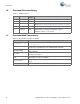
J4 Pin PSoC 4 Signal PSoC 4 Description J4_01 P0[4] D0(RX) J4_02 P0[5] D1(TX) J4_03 P0[7] D2 J4_04 P3[7] D3(PWM) J4_05 P0[0] D4 J4_06 P3[5] D5(PWM) J4_07 P1[0] D6(PWM) J4_08 P2[7] D7 J12 Pin Kit Signal PSoC 4 Description J12_01 P3[1] MISO J12_02 PSoC 4_VDD VDD J12_03 P0[6] SCK J12_04 P3[0] MOSI J12_05 /XRES PSoC 4 RESET J12_06 GND GND A.2.
A.2.3 PSoC 5LP GPIO Header (J8) J8 is a 2×6 header that connects PSoC 5LP pins to support GPIO controls for custom PSoC 5LP projects.
A.4 Use of Zero-ohm Resistors and No Load Unit Resistor Usage Power supply R2 Solder zero-ohm resistors to access voltage from VBUS (USB). I2C connection between PSoC 5LP and PSoC 4 R24 and R25 Unsolder the resistors to communicate with an external PSoC using the PSoC 5LP. Removing these will disable the PSoC 4 programming by the PSoC 5LP device. PSoC 4/external PSoC program/ debug header R32, R33, and R34 Unsolder the resistors to disconnect SWD lines from the PSoC 4.
A.6 No. Bill of Materials (BOM) Qty Reference Value Description Manufacturer Mfr Part Number PCB,3.32"x2.1" CAF resistant High Tg ENIG finish, 4 layer, Color = RED, Silk = Cypress WHITE. 1 CAP CER 2200PF 50V 5% NP0 0805 Murata GRM2165C1H222JA0 1D C2,C7,C12,C14,C15,C 17,C20,C21,C22,C24, 0.1 uFd C25,C27 CAP .1UF 16V CERAMIC Y5V 0402 Panasonic - ECG ECJ-0EF1C104Z 11 C3,C5,C8,C10,C11,C1 3,C18,C19,C23,C26,C 1.0 uFd 28 CAP CERAMIC 1.
No. Qty Reference Value Description Manufacturer Mfr Part Number 23 1 J13 2p_jumper CONN HEADER VERT SGL 2POS GOLD 3M 961102-6404-AR 24 3 Q1,Q2,Q3 PMOS MOSFET P-CH 30V 3.8A SOT23-3 Diodes Inc DMP3098L-7 25 1 R3 560 RES 560 1/8W 5% 0805 SMD Panasonic - ECG ERJ-6GEYJ561V 26 12 R4,R11,R12,R14,R15, R16,R24,R25,R32,R33 ZERO ,R34,R45 RES 0.0 1/10W 0603 SMD Panasonic-ECG ERJ-3GEY0R00V 27 1 R5 ZERO RES 0.
No. Qty Reference Value Description 50 1 J5 6X1 RECP RA 51 1 J7 50MIL CONN HEADER 10 PIN 50MIL KEYED Samtec KEYED SMD SMD 52 1 J11 2 PIN HDR CONN HEADER FEMALE 2POS .1" GOLD Sullins Connector Solutions PPPC021LFBN-RC 53 1 J12 3x2 RECPT CONN HEADER FMAL 6PS .1" DL GOLD Sullins Connector Solutions PPPC032LFBN-RC 54 5 R1,R2,R7,R44,R46 ZERO RES 0.0 1/10W 0603 SMD Panasonic-ECG ERJ-3GEY0R00V 55 1 R6 ZERO RES 0.