
Specifications

34 CY8CKIT-042 PSoC 4 Pioneer Kit Guide, Doc. # 001-86371 Rev. *D
Hardware
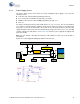
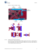
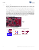
4.3.3.1 Protection Circuit
The power supply rail has reverse-voltage, over-voltage, short circuits, and excess current protection
features, as seen in Figure 4-4.
■ The Schottky diode (D1) ensures power cannot be supplied to the 5-V domain of the board from
the I/O header.
■ The series protection diode (D2) ensures VIN (power supply from the I/O header) does not back
power the USB.
■ The Schottky diode (D3) ensures 3.3 V from I/O header does not back power the LDO.
■ The series protection diode (D4) ensures that the reverse-voltage cannot be supplied from the
VIN to the regulator input.
■ A PTC resettable fuse is connected to protect the computer's USB ports from shorts and over-
current.
■ The MOSFET-based protection circuit provides over-voltage and reverse-voltage protection to
the 3.3-V rail. The PMOS Q1 protects the board components from a reverse-voltage condition.
The PMOS Q2 protects the PSoC from an over-voltage condition. The PMOS Q2 will turn off
when a voltage greater than 4.2 V is applied, protecting the PSoC 4.
■ The output voltage of the LDO is adjusted such that it takes into account the voltage drop across
the Schottky diode and provides 3.3 V.
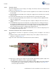
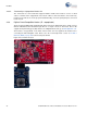
4.3.3.2 Procedure to Measure PSoC 4 Current Consumption
The following three methods are supported for measuring current consumption of the PSoC 4
device.
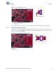
■ When the board is powered through the USB port (J10), remove jumper J13 and connect an
ammeter, as shown in Figure 4-5.
Figure 4-5. PSoC 4 Current Measurement when Powered from USB Port
■ When using a separate power supply for the PSoC 4 with USB powering (regulator output on the
USB supply must be within 0.5 V of the separate power supply).
❐ Remove jumper J13. Connect the positive terminal of voltage supply to the positive terminal of
the ammeter and the negative terminal of the ammeter to the lower pin of J13. Figure 4-6
shows the required connections.