
Specifications

CY8CKIT-042 PSoC 4 Pioneer Kit Guide, Doc. # 001-86371 Rev. *D 35
Hardware
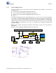
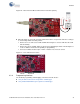
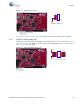
Figure 4-6. PSoC 4 Current Measurement when Powered Separately
■ When the PSoC 4 is powered separately and the PSoC 5LP is not powered, make these changes
to avoid leakage while measuring current:
❐ Remove the zero-ohm resistors R24 and R25. Removing these resistors will affect the USB-
I2C functionality.
❐ Remove R11, R15, and R16, which are meant for programming the PSoC 4. Removing these
resistors disables the PSoC 5LP capability for programming.
❐ Connect an ammeter between pins 1 and 2 of header J13 to measure current.
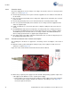
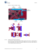
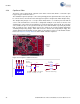
Figure 4-7. Zero-ohm Resistor Position
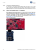
4.3.4 Programming Interface
The kit allows programming and debugging of the PSoC 4 in two modes:
■ Using the Onboard PSoC 5LP Programmer and Debugger
■ Using CY8CKIT-002 MiniProg3 Programmer and Debugger
VOLTAGE
SOURCE