
Specifications

40 CY8CKIT-042 PSoC 4 Pioneer Kit Guide, Doc. # 001-86371 Rev. *D
Hardware
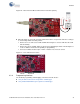
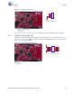
4.3.8 CapSense Slider
The kit has a five-segment linear capacitive touch slider on the board, which is connected to pins
P1[1] to P1[5] of the PSoC 4 device.
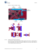
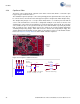
The modulation capacitor (Cmod) is connected to pin P4[2] and an optional bleeder resistor (R1) can
be connected across the Cmod. This board supports CapSense designs that enable waterproofing.
The waterproofing design uses a concept called shield, which is a conductor placed around the
sensors. This shield must be connected to a designated shield pin on the device to function. The
shield must be connected to the ground when not used. On the PSoC 4 Pioneer Kit, the connection
of the shield to the pin or to the ground is made by resistors R44 and R45, respectively. By default,
R45 is mounted on the board, which connects the shield to the ground. Populate R44 when
evaluating waterproofing designs, which will connect the shield to the designated pin, P0[1]. This
shield is different from the Arduino shields, which are boards that connect over the Arduino header.
Refer to the CapSense Design Guide for further details related to CapSense.
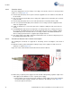
Figure 4-13. CapSense Slider
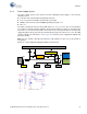
Figure 4-14. CapSense Slider Connection
P1_1
P1_2
P1_3
P1_4
P1_5
R17
560 ohm
R20
560 ohm
R21
560 ohm
R19
560 ohm
CSS1
CapSense Slider 5 Seg
1
2
3
4
5
R18
560 ohm
Shunt
Resistor
CAPSENSE TUNING CIRCUITRY
Default Loaded For CSD
NO LOAD
Shield Setting
P4_2
ShieldP0_1
0603
R45 ZERO
C1
2200 pF
0603
R44 ZERO
R1
NO LOAD