
Specifications

CY8CKIT-042 PSoC 4 Pioneer Kit Guide, Doc. # 001-86371 Rev. *D 55
Code Examples
5.4.1.3 Flow Chart
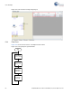
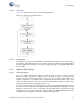
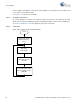
Figure 5-19 shows the flow chart of code implemented in main.c.
Figure 5-19. CapSense Project Flow Chart
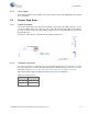
5.4.1.4 Verify Output
The brightness of the green and red LEDs are varied based on the position of the user’s finger on
the CapSense slider. When the finger is on segment 5 (P1[5]) of the slider, the green LED is brighter
than the red LED; when the finger is on segment 1 (P1[1]) of the slider, the red LED is brighter than
the green LED.
5.4.2 CapSense (With Tuning)
5.4.2.1 Project Description
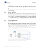
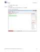
This code example demonstrates CapSense tuning on PSoC 4 using the "Tuner" to monitor
CapSense outputs. The CapSense outputs such as rawcounts, baseline, and signal (difference
count) can be monitored on the Tuner GUI. The project uses the auto-tuning feature, which sets all
CapSense parameters to the optimum values automatically. The parameter settings can be moni-
tored in the GUI but cannot be altered. In the manual tuning method, parameter settings can be
changed in the GUI and the resulting output can be seen.
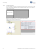
The code example uses the five-segment CapSense slider on the board. Each capacitive sensor on
the slider is scanned using Cypress's CapSense Sigma Delta (CSD) algorithm implemented in the
CapSense component. The code uses tuner APIs. The tuner API CapSense_TunerComm() is used
in the main loop to scan sensors, which also sends the CapSense variables RawCounts, Baseline,
and Difference Counts (Signal) to the PC GUI through I2C communication.