
Specifications

56 CY8CKIT-042 PSoC 4 Pioneer Kit Guide, Doc. # 001-86371 Rev. *D
Code Examples
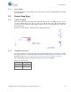
In this example, the brightness of the green and red LEDs are varied, based on the position of the
user's finger on the CapSense slider.
See Figure 5-17 for the project schematic.
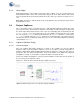
5.4.2.2 Hardware Connections
No specific hardware connections are required for this project because all connections are hard-
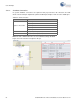
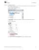
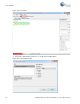
wired on the board. Open CapSense.cydwr in the Workspace Explorer and select the suitable pins.
See Table 5-4 and Figure 5-18 for the CapSense project pin connections.
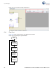
5.4.2.3 Flow Chart
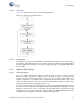
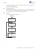
Figure 5-20. CapSense with Tuning Flow Chart
Start
Initialise and start the
PWM and CapSense
Tuner
Start Tuner
communication
Get the finger position on
the slider
Set the PWM output width to
adjust the brightness of the
RGB LED