
Specifications


84 CY8CKIT-042 PSoC 4 Pioneer Kit Guide, Doc. # 001-86371 Rev. *D
Advanced Topics
6.3 Developing Applications for PSoC 5LP
The PSoC 4 Pioneer Kit has an onboard PSoC 5LP whose primary function is that of a programmer
and a bridge. You can build either a normal project or a bootloadable project using the PSoC 5LP.
The PSoC 5LP connections in the Pioneer board are summarized in Figure 6-30. J8 is the I/O con-
nector (see section 4.3.7 PSoC 5LP GPIO Header (J8)). The USB (J10) is connected and used as
the PC interface. But you can still use this USB connection to create customized USB designs.
The programming header (J7) is meant for standalone programming. This header needs to be
populated. See the 'No Load Components' section in A.6 Bill of Materials (BOM) on page 108.
Figure 6-30. PSoC 5LP Block Diagram
6.3.1 Building a Bootloadable Project for PSoC 5LP
All bootloadable applications developed for the PSoC 5LP should be based on the bootloader hex
file, which is programmed onto the kit. The bootloader hex file is available in the kit files or can be
downloaded from the kit web page.
The hex files are included in the following kit installer directory:
<Install Path>\CY8CKIT-042 PSoC 4 Pioneer Kit\
<version>\Firmware\Programmer\KitProg_Bootloader
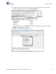
Figure 6-31. KitProg Bootloader Hex File Location
To build a bootloadable application for the PSoC 5LP, follow this procedure:
PSoC 5LP
Mini USB (J10)
PSoC 5LP
I/O Header
(J8)
10-pin SWD
programming
and debugging
header
(J7)
D+
D-
P15_6
P15_7
XRES
SWDIO
SWDCLK
SWO
TDI
XRES
P1_0
P1_1
P1_3
P1_4
J8_2
J8_4
J8_3
J8_5
J8_8
J8_7
J8_6
J8_9
J8_10
J8_12
P1_2 P0_0
P0_1 P3_4 P3_5 P3_6 P3_7
P12_6
P12_7
P3_0