
Specifications


CY8CKIT-042 PSoC 4 Pioneer Kit Guide, Doc. # 001-86371 Rev. *D 91
Advanced Topics
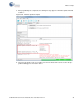
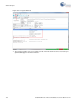
10.If bootload is successful, the log of the tool displays "Successful"; otherwise, it displays "Failed"
and a statement for the failure.
Notes:
1. The PSoC 5LP pins are brought to the PSoC 5LP GPIO header (J8). These pins are selected to
support high-performance analog and digital projects. See A.2 Pin Assignment Table on
page 104 for pin information.
2. Take care when allocating the PSoC 5LP pins for custom applications. For example, P2[0]–P2[4]
are dedicated for programming the PSoC 4. Refer to A.1 CY8CKIT-042 Schematics on page 101
before allocating the pins.
3. When a normal project is programmed onto the PSoC 5LP, the initial capability of the PSoC 5LP
to act as a programmer, USB-UART bridge, or USB-I2C bridge in not available.
4. The status LED does not function unless used by the custom project.
For additional information on bootloaders, refer to Cypress application note, AN73503 - USB HID
Bootloader for PSoC 3 and PSoC 5LP.