CMSI-424E HDBaseT™ 4×4 HDMI Matrix over 4 CAT5e/6/7 with 2 HDMI Outputs 5-Play™ Operation Manual
DISCLAIMERS The information in this manual has been carefully checked and is believed to be accurate. Cypress Technology assumes no responsibility for any infringements of patents or other rights of third parties which may result from its use. Cypress Technology assumes no responsibility for any inaccuracies that may be contained in this document. Cypress also makes no commitment to update or to keep current the information contained in this document.
SAFETY PRECAUTIONS Please read all instructions before attempting to unpack, install or operate this equipment and before connecting the power supply. Please keep the following in mind as you unpack and install this equipment: • Always follow basic safety precautions to reduce the risk of fire, electrical shock and injury to persons. • To prevent fire or shock hazard, do not expose the unit to rain, moisture or install this product near water. • Never spill liquid of any kind on or into this product.
CONTENTS 1. Introduction �������������������������������������������� 1 2. Applications ������������������������������������������� 1 3. Package Contents �������������������������������� 1 4. System Requirements ���������������������������� 2 5. Features �������������������������������������������������� 2 6. Operation Controls and Functions ������� 3 6.1 Front Panel �����������������������������������������3 6.2 Rear Panel �����������������������������������������4 6.
1. INTRODUCTION The HDBaseT™ 4 by 4 HDMI Matrix over CAT5e/6/7 with two additional simultaneous HDMI outputs supports the transmission of video (resolutions up to 1080p Full HD and 1920x1200@60Hz), multi-channel digital audio and control via IR, RS-232 or Web GUI/Telnet IP from four high definition sources to four HDBaseT outputs over a single CAT5e/6/7 cable (up to 100m) for each output. Output A and C have additional mirrored HDMI outputs. It supports high resolution digital audio formats such as LPCM 7.
4. SYSTEM REQUIREMENTS • HDMI equipped source devices, connect with HDMI cables or DVI equipped source, connect with DVI to HDMI cables • HDMI equipped displays (TVs or monitors) or HDMI equipped AV receivers, connect with HDMI cables • Industry standard CAT5e/6/7 cables • HDBaseT™ Receivers (i.e. CH-506RX, CH-507RX or CH-1109RX) 5. FEATURES • HDMI, HDCP 1.
6. OPERATION CONTROLS AND FUNCTIONS 6.1 Front Panel POWER LOCK MENU CMSI-424E 4X4 HDMI MATRIX 1 2 3 4 5 A 1 B 2 OUT C 3 D 4 IN 6 1 LCM : Displays the setting information of each input and output setting. 2 IR Window: IR Receiver window (accepts the remote control signal of this device only). 3 POWER: Press this button to power the device on/off. The LED will illuminate green when the power is on, red when it is in 'Standby' mode.
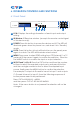
6.2 Rear Panel 4 A 7 B 1 9 2 C 4 3 D RS232 HDMI OUT CAT5e/6 OUT CAT5e/6 OUT IR IN IR OUT IR OUT IR IN IR OUT IR IN IR OUT HDMI OUT HDMI IN 1 2 3 CAT5e/6 OUT ALL IR OUT GND GND V+ CAT5e/6 OUT 2 1 4 3 +V GND IR IN SERVICE IP & ETHERNET 1 IR IN HDMI IN 2 HDMI IN 3 6 5 HDMI IN 4 DC 24V 8 10 11 1 RS-232: Connect to a PC or control system with D-Sub 9-pin cable for the transmission of RS-232 commands.
8 IR OUT 1~4: Connect the IR blasters for IR signal transmission. Place the IR blaster in direct line-of-sight of the equipment to be controlled. 9 ALL IR OUT: Connect to the IR blaster for IR signal transmission of the source or display equipment. Place the IR blaster in direct line-ofsight of the equipment to be controlled. 10 ALL IR IN: Connect to the IR extender for IR signal reception of the remote control of this device or the source and display equipment.
6.5 IR Pin Assignment IR Blaster 1 Power 5 V 2 IR Blaster Signal 3 NC IR Extender 1 IR Signal 2 Power 5 V 3 Grounding 6.
6.7 RS-232 and Telnet Commands COMMAND DESCRIPTION A1~A4 Switch output A to 1~4 B1~B4 Switch output B to 1~4 C1~C4 Switch output C to 1~4 D1~D4 Switch output D to 1~4 AB...1~CD...4 Switch output ABCD... to 1~4 SETIP Setting IP. SubNet.
6.8 Telnet Control Before attempting to use the Telnet control, ensure that both the Matrix (via the LAN/Control port) and the PC/Laptop or control system being used are connected to the same active network. To access the Telnet control in Windows 7, click on the 'Start' menu and type 'cmd' in the Search Field then press Enter (see below for reference). Under Windows XP, go to the 'Start' menu and click on 'Run', type 'cmd' then press Enter.
Once in the Command Line Interface (CLI) type 'telnet' along with the IP address of the unit you wish to control and '23' then hit Enter (see below for reference). This will bring us into the device which we wish to control. Note: The IP address of the Matrix can be displayed on the device's LCM monitor by pressing the Menu button twice. Type 'HELP' to list the available commands (see below for reference). Type 'IPCONFIG' To show all IP configurations.
6.9 Web GUI Control On a PC/Laptop or control system that is connected to the same active network as the Matrix, open a web browser and type device's IP address on the web address entry bar. The browser will display the device's status, and the control and user settings pages. Click on the 'Control' tab to control power, input/output ports, EDID and reset mode.
Click on the 'User Setting' tab allows you to reset the IP configuration. The system will ask for a reboot of the device every time any of the settings are changed. The IP address needed to access the Web GUI control will also need to be changed accordingly on the web address entry bar.
7.
8. SPECIFICATIONS Video Bandwidth 225 MHz/6.75 Gbps Input Ports 4×HDMI, 5×IR Extender, 1×LAN/CONTROL, 1×RS-232, 1×Mini-USB Type B(for firmware update only) Output Ports 4×CAT5e/6/7, 2×HDMI, 5×IR Blaster ESD Protection Human body model: ±8 kV (air-gap discharge) ±4 kV (contact discharge) Power Supply 24 V/3.
CYPRESS TECHNOLOGY CO., LTD Home page: http://www.cypress.com.