CMLUX-88S 8 by 8 HDMI V1.
Disclaimers The information in this manual has been carefully checked and is believed to be accurate. Cypress Technology assumes no responsibility for any infringements of patents or other rights of third parties which may result from its use. Cypress Technology assumes no responsibility for any inaccuracies that may be contained in this document. Cypress also makes no commitment to update or to keep current the information contained in this document.
Safety Precautions Please read all instructions before attempting to unpack or install or operate this equipment, and before connecting the power supply. Please keep the following in mind as you unpack and install this equipment: Always follow basic safety precautions to reduce the risk of fire, electrical shock and injury to persons. To prevent fire or shock hazard, do not expose the unit to rain, moisture or install this product near water.
Table of Contents I. Rack Installation Guideline ..………...……………...…........….…… 1 1. Introduction ……………………..……………………...…........….……. 2 2. Applications …………………..………………….……...................….. 2 3. Package Contents ………………………...........……….................… 2 4. System Requirements ……………..……….........………............……. 2 5. Features …………………………………………......……........…...…… 3 6. Specifications ………………………………...……..........………....…. 4 7. Operation Controls and Functions ……………...……............
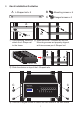
I. Rack Installation Guideline A L-Shaped rail x 2 B Mounting screws x 4 C Flanged screws x 4 A B B X4 ① Use Mounting screws to ② Make sure the L-Shaped rail and the attach the L-Shape rail Mounting screws are properly aligned, to the frame. with two screws per L-Shaped rail. A A CMLUX-88S ③ Slide the device on top of the L-Shaped rails. C CMLUX-88S 8x8 HDMI v1.
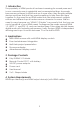
1. Introduction The popularity of HDMI products has been increasing for several years and is now commonly seen in residential and commercial settings. As people become accustomed to HDMI and use it more often, they acquire multiple devices and then find that they need something to help them link them together. So the need for an HDMI matrix that can interconnect multiple sources and different inputs has become an obsession for some. Well no need to worry because our “HDMI V1.
5. Features HDMI 1.3, HDCP 1.1 and DVI 1.0 compliant Supports digital video formats in Deep Color 10 bits and new lossless compressed (Dolby TrueHD, Dolby Digital Plus and DTS HD Master Audio) digital audio The HDMI input is compensated, clock/phase adjusted and jitter free so all the user sees is a high quality HDMI signal.
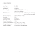
6. Specifications Input Ports 8 x HDMI Output Ports 8 x HDMI IR Frquency 20~60KHz Power Supply 24VDC/6.
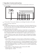
7. Operation Controls and Functions The following sections describe the hardware components of the unit. 7.1 Front Panel ① ② ③ ④ ⑤ ⑥ ⑦ ⑧ ⑨ ⑩ ① LCM monitor: This monitor displays your settings information with each output and input selection. ② IR sensor. ③ POWER: Press this button to turn the system on. Once the system turns on the LED will turn Green and when entering Standby Mode it will turn Red. Once the system turns on the LED will turn Green and when entering Standby Mode it will turn Red.
⑤ LOCK: Press this button to lock all the functions and press it again to release the lock. When LED turns Green, the lock is activated and when it turns red the key lock has been released. ⑥ ENTER: Press this button after each and every selection to confirm the setting. If this button is not pressed after 20 seconds the selection will be cancelled. ⑦ ALL: Press this button to set all the outputs to display with the same input.
7.2 Rear Panel ①② ③ ④ ⑤ ⑥ ⑦ ① HDMI OUTPUT A~H: These slots are where you connect the HDMI displays. ② SERVICE: This slot is where you connect a D-sub 9 male pin connector cable to your host, in order to upgrade your firmware. ③ RS-232: This slot is where you connect a D-sub 9 female pin connector cable to your host so you can control an 8x8 HDMI Matrix.
8. Remote Control This remote control can be set with multipal format according to the dipswitch setting. There are total of four dipswitches with mainly two kinds of settings. When dipswitches are all set to ON/↑ the remote control is able to control all outputs and all inputs. For example, when output A wish to select input 5. Press 1 first and wait for a second then press 5, the output display A will display input source 5’s image instantly. Other settings referring to below section 8.2 section 8.
9. IR Pin Assignment 9.1 IR Receiver ① IR signal ② Power 5V ③ Grounding ① ②③ 10. RS-232 Protocols 10.
10.
PORT 47 Output D select Input7 PORT 48 Output D select Input8 PORT 51 Output E select Input1 PORT 52 Output E select Input2 PORT 53 Output E select Input3 PORT 54 Output E select Input4 PORT 55 Output E select Input5 PORT 56 Output E select Input6 PORT 57 Output E select Input7 PORT 58 Output E select Input8 PORT 61 Output F select Input1 PORT 62 Output F select Input2 PORT 63 Output F select Input3 PORT 64 Output F select Input4 PORT 65 Output F select Input5 PORT 66 Output F
11.
A Acronyms Acronym Complete Term DTS Digital Theater System DVI Digital Visual Interface EDID Extedned Display Identification Data HDCP High-bandwidth Digital Content Protection HDMI High-Definition Multimedia Interface HDTV High-Definition Television LCM Liquid Crystal Monitor USB Universal Serial Bus UXGA Ultra Extended Graphics Array VGA Video Graphics Array 13
CYPRESS TECHNOLOGY CO., LTD. Home page: http://www.cypress.com.