
User manual
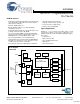

CY7C67200
Document #: 38-08014 Rev. *G Page 10 of 78
Registers
Some registers have different functions for a read vs. a write
access or USB host vs. USB device mode. Therefore,
registers of this type have multiple definitions for the same
address.
The default register values listed in this data sheet may be
altered to some other value during BIOS initialization. Refer to
the BIOS documentation for Register initialization information.
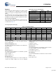
Processor Control Registers
There are eight registers dedicated to general processor
control. Each of these registers is covered in this section and
is summarized in Table 16 .
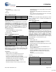
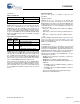
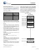
CPU Flags Register [0xC000] [R]
Figure 7. CPU Flags Register
Register Description
The CPU Flags register is a read only register that gives
processor flags status.
Global Interrupt Enable (Bit 4)
The Global Interrupt Enable bit indicates if the Global Inter-
rupts are enabled.
1: Enabled
0: Disabled
Negative Flag (Bit 3)
The Negative Flag bit indicates if an arithmetic operation
results in a negative answer.
1: MS result bit is ‘1’
0: MS result bit is not ‘1’
Overflow Flag (Bit 2)
The Overflow Flag bit indicates if an overflow condition has
occurred. An overflow condition can occur if an arithmetic
result was either larger than the destination operand size (for
addition) or smaller than the destination operand should allow
for subtraction.
1: Overflow occurred
0: Overflow did not occur
Carry Flag (Bit 1)
The Carry Flag bit indicates if an arithmetic operation resulted
in a carry for addition, or borrow for subtraction.
1: Carry/Borrow occurred
0: Carry/Borrow did not occur
Zero Flag (Bit 0)
The Zero Flag bit indicates if an instruction execution resulted
in a ‘0’.
1: Zero occurred
0: Zero did not occur
Table 16.Processor Control Registers
Register Name Address R/W
CPU Flags Register 0xC000 R
Register Bank Register 0xC002 R/W
Hardware Revision Register 0xC004 R
CPU Speed Register 0xC008 R/W
Power Control Register 0xC00A R/W
Interrupt Enable Register 0xC00E R/W
Breakpoint Register 0xC014 R/W
USB Diagnostic Register 0xC03C W
Bit # 15 14 13 12 11 10 9 8
Field Reserved...
Read/Write - - - - - - - -
Default 0 0 0 0 0 0 0 0
Bit # 7 6 5 4 3 2 1 0
Field
...Reserved Global
Interrupt
Enable
Negative
Flag
Overflow
Flag
Carry
Flag
Zero
Flag
Read/Write - - - R R R R R
Default 0 0 0 X X X X X
[+] Feedback