
User manual


CY7C67200
Document #: 38-08014 Rev. *G Page 15 of 78
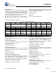
UART Interrupt Enable (Bit 3)
The UART Interrupt Enable bit enables or disables the
following UART hardware interrupts: UART TX and UART RX.
1: Enable UART interrupt
0: Disable UART interrupt
GPIO Interrupt Enable (Bit 2)
The GPIO Interrupt Enable bit enables or disables the General
Purpose IO Pins Interrupt (See the GPIO Control Register).
When GPIO bit is reset, all pending GPIO interrupts are also
cleared.
1: Enable GPIO interrupt
0: Disable GPIO interrupt
Timer 1 Interrupt Enable (Bit 1)
The Timer 1 Interrupt Enable bit enables or disables the
TImer1 Interrupt Enable. When this bit is reset, all pending
Timer 1 interrupts are cleared.
1: Enable TM1 interrupt
0: Disable TM1 interrupt
Timer 0 Interrupt Enable (Bit 0)
The Timer 0 Interrupt Enable bit enables or disables the
TImer0 Interrupt Enable. When this bit is reset, all pending
Timer 0 interrupts are cleared.
1: Enable TM0 interrupt
0: Disable TM0 interrupt
Reserved
All reserved bits must be written as ‘0’.
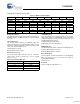
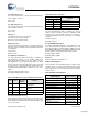
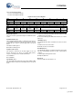
Breakpoint Register [0xC014] [R/W]
Figure 13. Breakpoint Register
Register Description
The Breakpoint Register holds the breakpoint address. When the program counter match this address, the INT127 interrupt
occurs. To clear this interrupt, a zero value must be written to this register.
Address (Bits [15:0])
The Address field is a 16-bit field containing the breakpoint address.
Bit # 15 14 13 12 11 10 9 8
Field Address...
Read/Write R/W R/W R/W R/W R/W R/W R/W R/W
Default 0 0 0 0 0 0 0 0
Bit # 7 6 5 4 3 2 1 0
Field ...Address
Read/Write R/W R/W R/W R/W R/W R/W R/W R/W
Default 0 0 0 0 0 0 0 0
[+] Feedback