
User manual


CY7C67200
Document #: 38-08014 Rev. *G Page 16 of 78
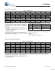
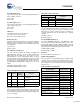
USB Diagnostic Register [0xC03C] [R/W]
Figure 14. USB Diagnostic Register
Register Description
The USB Diagnostic Register provides control of diagnostic
modes. It is intended for use by device characterization tests,
not for normal operations. This register is Read/Write by the
on-chip CPU but is write-only via the HPI port.
Port 2A Diagnostic Enable (Bit 15)
The Port 2A Diagnostic Enable bit enables or disables Port 2A
for the test conditions selected in this register.
1: Apply any of the following enabled test conditions: J/K,
DCK, SE0, RSF, RSL, PRD
0: Do not apply test conditions
Port 1A Diagnostic Enable (Bit 15)
The Port 1A Diagnostic Enable bit enables or disables Port 1A
for the test conditions selected in this register.
1: Apply any of the following enabled test conditions: J/K,
DCK, SE0, RSF, RSL, PRD
0: Do not apply test conditions
Pull-down Enable (Bit 6)
The Pull-down Enable bit enables or disables full-speed
pull-down resistors (pull down on both D+ and D–) for testing.
1: Enable pull-down resistors on both D+ and D–
0: Disable pull-down resistors on both D+ and D–
LS Pull-up Enable (Bit 5)
The LS Pull-up Enable bit enables or disables a low-speed
pull-up resistor (pull up on D–) for testing.
1: Enable low-speed pull-up resistor on D–
0: Pull-up resistor is not connected on D–
FS Pull-up Enable (Bit 4)
The FS Pull-up Enable bit enables or disables a full-speed
pull-up resistor (pull up on D+) for testing.
1: Enable full-speed pull-up resistor on D+
0: Pull-up resistor is not connected on D+
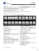
Force Select (Bits [2:0])
The Force Select field bit selects several different test
condition states on the data lines (D+/D–). See Table 19 for
details.
Reserved
All reserved bits must be written as ‘0’.
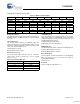
Timer Registers
There are three registers dedicated to timer operations. Each
of these registers are discussed in this section and are
summarized in Table 20.
Bit # 15 14 13 12 11 10 9 8
Field
Reserved Port 2A
Diagnostic
Enable
Reserved Port 1A
Diagnostic
Enable
Reserved...
Read/Write - R/W - R/W - - - -
Default 0 0 0 0 0 0 0 0
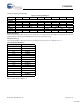
Bit # 7 6 5 4 3 2 1 0
Field
...Reserved Pull-down
Enable
LS Pull-up
Enable
FS Pull-up
Enable
Reserved Force Select
Read/Write - R/W R/W R/W - R/W R/W R/W
Default 0 0 0 0 0 0 0 0
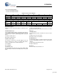
Table 19.Force Select Definition
Force Select [2:0] Data Line State
1xx Assert SE0
01x Toggle JK
001 Assert J
000 Assert K
Table 20.Timer Registers
Register Name Address R/W
Watchdog Timer Register 0xC00C R/W
Timer 0 Register 0xC010 R/W
Timer 1 Register 0xC012 R/W
[+] Feedback