
User manual


CY7C67200
Document #: 38-08014 Rev. *G Page 17 of 78
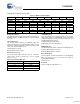
Watchdog Timer Register [0xC00C] [R/W]
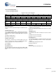
Figure 15. Watchdog Timer Register
Register Description
The Watchdog Timer register provides status and control over
the Watchdog timer. The Watchdog timer can also interrupt the
processor.
Timeout Flag (Bit 5)
The Timeout Flag bit indicates if the Watchdog timer has
expired. The processor can read this bit after exiting a reset to
determine if a Watchdog timeout occurred. This bit is cleared
on the next external hardware reset.
1: Watchdog timer expired
0: Watchdog timer did not expire
Period Select (Bits [4:3])
The Period Select field is defined in Table 21. If this time
expires before the Reset Strobe bit is set, the internal
processor is reset.
Lock Enable (Bit 2)
The Lock Enable bit does not allow any writes to this register
until a reset. In doing so the Watchdog timer can be set up and
enabled permanently so that it can only be cleared on reset
(the WDT Enable bit is ignored).
1: Watchdog timer permanently set
0: Watchdog timer not permanently set
WDT Enable (Bit 1)
The WDT Enable bit enables or disables the Watchdog timer.
1: Enable Watchdog timer operation
0: Disable Watchdog timer operation
Reset Strobe (Bit 0)
The Reset Strobe is a write-only bit that resets the Watchdog
timer count. It must be set to ‘1’ before the count expires to
avoid a Watchdog trigger
1: Reset Count
Reserved
All reserved bits must be written as ‘0’.
Bit # 15 14 13 12 11 10 9 8
Field Reserved...
Read/Write R/W R/W R/W R/W R/W R/W R/W R/W
Default 0 0 0 0 0 0 0 0
Bit # 7 6 5 4 3 2 1 0
Field
...Reserved Timeout
Flag
Period
Select
Lock
Enable
WDT
Enable
Reset
Strobe
Read/Write R/W R/W R/W R/W R/W R/W R/W W
Default 0 0 0 0 0 0 0 0
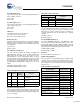
Table 21.Period Select Definition
Period Select[4:3] WDT Period Value
00 1.4 ms
01 5.5 ms
10 22.0 ms
11 66.0 ms
[+] Feedback