
User manual


CY7C67200
Document #: 38-08014 Rev. *G Page 29 of 78
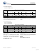
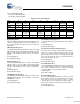
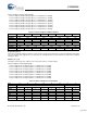
Figure 30. Device n Endpoint n Control Register
Register Description
The Device n Endpoint n Control register provides control over
a single EP in device mode. There are a total of eight
endpoints for each of the two ports. All endpoints have the
same definition for their Device n Endpoint n Control register.
IN/OUT Ignore Enable (Bit 6)
The IN/OUT Ignore Enable bit forces endpoint 0 (EP0) to
ignore all IN and OUT requests. This bit must be set so that
EP0 only excepts Setup packets at the start of each transfer.
This bit must be cleared to except IN/OUT transactions. This
bit only applies to EP0.
1: Ignore IN/OUT requests
0: Do not ignore IN/OUT requests
Sequence Select (Bit 6)
The Sequence Select bit determines whether a DATA0 or a
DATA1 will be sent for the next data toggle. This bit has no
effect on receiving data packets, sequence checking must be
handled in firmware.
1: Send a DATA1
0: Send a DATA0
Stall Enable (Bit 5)
The Stall Enable bit sends a Stall in response to the next
request (unless it is a setup request, which are always
ACKed). This is a sticky bit and continues to respond with
Stalls until cleared by firmware.
1: Send Stall
0: Do not send Stall
ISO Enable (Bit 4)
The ISO Enable bit enables and disables an Isochronous
transaction. This bit is only valid for EPs 1–7 and has no
function for EP0.
1: Enable Isochronous transaction
0: Disable Isochronous transaction
NAK Interrupt Enable (Bit 3)
The NAK Interrupt Enable bit enables and disables the gener-
ation of an Endpoint n interrupt when the device responds to
the host with a NAK. The Endpoint n Interrupt Enable bit in the
Device n Interrupt Enable register must also be set. When a
NAK is sent to the host, the corresponding EP Interrupt Flag
in the Device n Status register will be set. In addition, the NAK
Flag in the Device n Endpoint n Status register will be set.
1: Enable NAK interrupt
0: Disable NAK interrupt
Direction Select (Bit 2)
The Direction Select bit needs to be set according to the
expected direction of the next data stage in the next trans-
action. If the data stage direction is different from what is set
in this bit, it will get NAKed and either the IN Exception Flag or
the OUT Exception Flag will be set in the Device n Endpoint n
Status register. If a setup packet is received and the Direction
Select bit is set incorrectly, the setup will be ACKed and the
Set-up Status Flag will be set (refer to the setup bit of the
Device n Endpoint n Status register for details).
1: OUT transfer (host to device)
0: IN transfer (device to host)
Enable (Bit 1)
The Enable bit must be set to allow transfers to the endpoint.
If Enable is set to ‘0’ then all USB traffic to this endpoint is
ignored. If Enable is set ‘1’ and Arm Enable (bit 0) is set ‘0’ then
NAKs will automatically be returned from this endpoint (except
setup packets, which are always ACKed as long as the Enable
bit is set).
1: Enable transfers to an endpoint
0: Do not allow transfers to an endpoint
Arm Enable (Bit 0)
The Arm Enable bit arms the endpoint to transfer or receive a
packet. This bit is cleared to ‘0’ when a transaction is complete.
1: Arm endpoint
0: Endpoint disarmed
Reserved
All reserved bits must be written as ‘0’.
Bit # 15 14 13 12 11 10 9 8
Field Reserved
Read/Write - - - - - - - -
Default X X X X X X X X
Bit # 7 6 5 4 3 2 1 0
Field
IN/OUT
Ignore
Enable
Sequence
Select
Stall
Enable
ISO
Enable
NAK
Interrupt
Enable
Direction
Select
Enable Arm
Enable
Read/Write R/W R/W R/W R/W R/W R/W R/W R/W
Default X X X X X X X X
[+] Feedback