
User manual

CY7C67200
Document #: 38-08014 Rev. *G Page 3 of 78
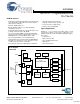
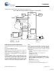
USB Interface
EZ-OTG has two built-in Host/Peripheral SIEs that each have
a single USB transceiver, meeting the USB 2.0 specification
requirements for full and low speed (high speed is not support-
ed). In Host mode, EZ-OTG supports two downstream ports;
each supports control, interrupt, bulk, and isochronous trans-
fers. In Peripheral mode, EZ-OTG supports one peripheral
port with eight endpoints for each of the two SIEs. Endpoint 0
is dedicated as the control endpoint and only supports control
transfers. Endpoints 1 though 7 support Interrupt, bulk (up to
64 bytes per packet), or isochronous transfers (up to 1023
bytes per packet size). EZ-OTG also supports a combination
of Host and Peripheral ports simultaneously, as shown in
Table 2.
USB Features
• USB 2.0 compatible for full and low speed
• Up to two downstream USB host ports
• Up to two upstream USB peripheral ports
• Configurable endpoint buffers (pointer and length), must
reside in internal RAM
• Up to eight available peripheral endpoints (1 control
endpoint)
• Supports Control, Interrupt, Bulk, and Isochronous transfers
• Internal DMA channels for each endpoint
• Internal pull up and pull down resistors
• Internal Series termination resistors on USB data lines
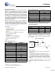
USB Pins
OTG Interface
EZ-OTG has one USB port that is compatible with the USB
On-The-Go supplement to the USB 2.0 specification. The USB
OTG port has various hardware features to support Session
Request Protocol (SRP) and Host Negotiation Protocol (HNP).
OTG is only supported on USB PORT 1A.
OTG Features
• Internal Charge Pump to supply and control VBUS
• VBUS Valid Status (above 4.4V)
• VBUS Status for 2.4V < VBUS < 0.8V
• ID Pin Status
• Switchable 2-Kohm internal discharge resistor on VBUS
• Switchable 500-ohm internal pull-up resistor on VBUS
• Individually switchable internal pull-up and pull-down
resistors on the USB data lines
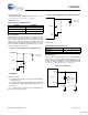
OTG Pins
General Purpose IO Interface
EZ-OTG has up to 25 GPIO signals available. Several other
optional interfaces use GPIO pins as well and may reduce the
overall number of available GPIOs.
GPIO Description
All Inputs are sampled asynchronously with state changes oc-
curring at a rate of up to two 48 MHz clock cycles. GPIO pins
are latched directly into registers, a single flip-flop.
Unused Pin Descriptions
Unused USB pins must be tri-stated with the D+ line pulled
high through the internal pull-up resistor and the D– line pulled
low through the internal pull-down resistor.
Unused GPIO pins must be configured as outputs and driven
low.
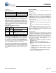
UART Interface
EZ-OTG has a built-in UART interface. The UART interface
supports data rates from 900 to 115.2K baud. It can be used
as a development port or for other interface requirements. The
UART interface is exposed through GPIO pins.
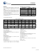
Table 2. USB Port Configuration Options
Port Configurations Port 1A Port 2A
OTG OTG –
OTG + 1 Host OTG Host
OTG + 1 Peripheral OTG Peripheral
1 Host + 1 Peripheral Host Peripheral
1 Host + 1 Peripheral Peripheral Host
2 Hosts Host Host
1 Host Host –
1 Host – Host
2 Peripherals Peripheral Peripheral
1 Peripheral Peripheral –
1 Peripheral – Peripheral
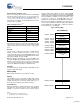
Table 3. USB Interface Pins
Pin Name Pin Number
DM1A F2
DP1A E3
DM2A C2
DP2A D3
Table 4. OTG Interface Pins
Pin Name Pin Number
DM1A F2
DP1A E3
OTGVBUS C1
OTGID F4
CSwitchA D1
CSwitchB D2
[+] Feedback