
User manual


CY7C67200
Document #: 38-08014 Rev. *G Page 34 of 78
Device n Interrupt Enable Register [R/W]
• Device 1 Interrupt Enable Register 0xC08C
• Device 2 Interrupt Enable Register 0xC0AC
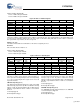
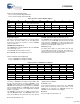
Figure 35. Device n Interrupt Enable Register
Register Description
The Device n Interrupt Enable register provides control over
device-related interrupts including eight different endpoint
interrupts.
VBUS Interrupt Enable (Bit 15)
The VBUS Interrupt Enable bit enables or disables the OTG
VBUS interrupt. When enabled this interrupt triggers on both
the rising and falling edge of VBUS at the 4.4V status (only
supported in Port 1A). This bit is only available for Device 1
and is a reserved bit in Device 2.
1: Enable VBUS interrupt
0: Disable VBUS interrupt
ID Interrupt Enable (Bit 14)
The ID Interrupt Enable bit enables or disables the OTG ID
interrupt. When enabled this interrupt triggers on both the
rising and falling edge of the OTG ID pin (only supported in
Port 1A). This bit is only available for Device 1 and is a
reserved bit in Device 2.
1: Enable ID interrupt
0: Disable ID interrupt
SOF/EOP Timeout Interrupt Enable (Bit 11)
The SOF/EOP Timeout Interrupt Enable bit enables or
disables the SOF/EOP Timeout Interrupt. When enabled this
interrupt triggers when the USB host fails to send a SOF or
EOP packet within the time period specified in the Device n
SOF/EOP Count register. In addition, the Device n Frame
register counts the number of times the SOF/EOP Timeout
Interrupt triggers between receiving SOF/EOPs.
1: SOF/EOP timeout occurred
0: SOF/EOP timeout did not occur
SOF/EOP Interrupt Enable (Bit 9)
The SOF/EOP Interrupt Enable bit enables or disables the
SOF/EOP received interrupt.
1: Enable SOF/EOP Received interrupt
0: Disable SOF/EOP Received interrupt
Reset Interrupt Enable (Bit 8)
The Reset Interrupt Enable bit enables or disables the USB
Reset Detected interrupt
1: Enable USB Reset Detected interrupt
0: Disable USB Reset Detected interrupt
EP7 Interrupt Enable (Bit 7)
The EP7 Interrupt Enable bit enables or disables an endpoint
seven (EP7) Transaction Done interrupt. An EPx Transaction
Done interrupt triggers when any of the following responses or
events occur in a transaction for the device’s given Endpoint:
send/receive ACK, send STALL, Timeout occurs, IN Exception
Error, or OUT Exception Error. In addition, the NAK Interrupt
Enable bit in the Device n Endpoint Control register can also
be set so that NAK responses triggers this interrupt.
1: Enable EP7 Transaction Done interrupt
0: Disable EP7 Transaction Done interrupt
EP6 Interrupt Enable (Bit 6)
The EP6 Interrupt Enable bit enables or disables an endpoint
six (EP6) Transaction Done interrupt. An EPx Transaction
Done interrupt triggers when any of the following responses or
events occur in a transaction for the device’s given Endpoint:
send/receive ACK, send STALL, Timeout occurs, IN Exception
Error, or OUT Exception Error. In addition, the NAK Interrupt
Enable bit in the Device n Endpoint Control register can also
be set so that NAK responses triggers this interrupt.
1: Enable EP6 Transaction Done interrupt
0: Disable EP6 Transaction Done interrupt
Bit # 15 14 13 12 11 10 9 8
Field
VBUS
Interrupt
Enable
ID Interrupt
Enable
Reserved SOF/EOP
Timeout
Interrupt Enable
Reserved SOF/EOP
Interrupt
Enable
Reset
Interrupt
Enable
Read/Write R/W R/W - - R/W - R/W R/W
Default 0 0 0 0 0 0 0 0
Bit # 7 6 5 4 3 2 1 0
Field
EP7 Interrupt
Enable
EP6 Interrupt
Enable
EP5 Interrupt
Enable
EP4 Interrupt
Enable
EP3 Interrupt
Enable
EP2 Interrupt
Enable
EP1 Interrupt
Enable
EP0 Interrupt
Enable
Read/Write R/W R/W R/W R/W R/W R/W R/W R/W
Default 0 0 0 0 0 0 0 0
[+] Feedback