
User manual


CY7C67200
Document #: 38-08014 Rev. *G Page 57 of 78
Transmit Interrupt Flag (Bit 1)
The Transmit Interrupt Flag is a read only bit that indicates a
byte mode transmit interrupt has triggered.
1: Indicates a byte mode transmit interrupt has triggered
0: Indicates a byte mode transmit interrupt has not triggered
Transfer Interrupt Flag (Bit 0)
The Transfer Interrupt Flag is a read only bit that indicates a
block mode interrupt has triggered.
1: Indicates a block mode interrupt has triggered
0: Indicates a block mode interrupt has not triggered
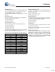
SPI Interrupt Clear Register [0xC0D0] [W]
Figure 65. SPI Interrupt Clear Register
Register Description
The SPI Interrupt Clear register is a write-only register that
allows the SPI Transmit and SPI Transfer Interrupts to be
cleared.
Transmit Interrupt Clear (Bit 1)
The Transmit Interrupt Clear bit is a write-only bit that clears
the byte mode transmit interrupt. This bit is self-clearing.
1: Clear the byte mode transmit interrupt
0: No function
Transfer Interrupt Clear (Bit 0)
The Transfer Interrupt Clear bit is a write-only bit that will clear
the block mode interrupt. This bit is self clearing.
1: Clear the block mode interrupt
0: No function
Reserved
All reserved bits must be written as ‘0’.
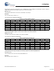
SPI CRC Control Register [0xC0D2] [R/W]
Figure 66. SPI CRC Control Register
Register Description
The SPI CRC Control register provides control over the CRC
source and polynomial value.
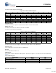
CRC Mode (Bits [15:14)
The CRCMode field selects the CRC polynomial as defined in
Table 35.
Bit # 15 14 13 12 11 10 9 8
Field Reserved
Read/Write - - - - - - - -
Default 0 0 0 0 0 0 0 0
Bit # 7 6 5 4 3 2 1 0
Field
Reserved Transmit
Interrupt Clear
Transfer
Interrupt Clear
Read/Write - - - - - - W W
Default 0 0 0 0 0 0 0 0
Bit # 15 14 13 12 11 10 9 8
Field
CRC Mode CRC
Enable
CRC
Clear
Receive
CRC
One in
CRC
Zero in
CRC
Reserved...
Read/Write R/W R/W R/W R/W R/W R R -
Default 0 0 0 0 0 0 0 0
Bit # 7 6 5 4 3 2 1 0
Field ...Reserved
Read/Write - - - - - - - -
Default 0 0 0 0 0 0 0 0
Table 35.CRC Mode Definition
CRCMode
[9:8]
CRC Polynomial
00 MMC 16-bit: X^16 + X^12 + X^5 + 1
(CCITT Standard)
01 CRC7 7-bit: X^7+ X^3 + 1
10 MST 16-bit: X^16+ X^15 + X^2 + 1
11 Reserved, 16-bit polynomial 1.
[+] Feedback