
User manual


CY7C67200
Document #: 38-08014 Rev. *G Page 61 of 78
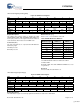
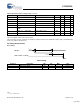
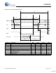
UART Control Register [0xC0E0] [R/W]
Figure 73. UART Control Register
Register Description
The UART Control register enables or disables the UART
allowing GPIO7 (UART_TXD) and GPIO6 (UART_RXD) to be
freed up for general use. This register must also be written to
set the baud rate, which is based on a 48-MHz clock.
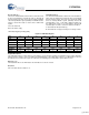
Scale Select (Bit 4)
The Scale Select bit acts as a prescaler that will divide the
baud rate by eight.
1: Enable prescaler
0: Disable prescaler
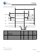
Baud Select (Bits [3:1])
Refer to Table 37 for a definition of this field.
UART Enable (Bit 0)
The UART Enable bit enables or disables the UART.
1: Enable UART
0: Disable UART. This allows GPIO6 and GPIO7 to be used
for general use
Reserved
All reserved bits must be written as ‘0’.
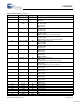
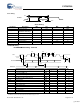
UART Status Register [0xC0E2] [R]
Figure 74. UART Status Register
Register Description
The UART Status register is a read-only register that indicates the status of the UART buffer.
Bit # 15 14 13 12 11 10 9 8
Field Reserved...
Read/Write - - - - - - - -
Default 0 0 0 0 0 0 0 0
Bit # 7 6 5 4 3 2 1 0
Field
...Reserved Scale
Select
Baud
Select
UART
Enable
Read/Write - - - R/W R/W R/W R/W R/W
Default 0 0 0 0 0 1 1 1
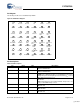
Table 37.UART Baud Select Definition
Baud Select [3:1]
Baud Rate
w/DIV8 = 0
Baud Rate
w/DIV8 = 1
000 115.2K baud 14.4K baud
001 57.6K baud 7.2K baud
010 38.4K baud 4.8K baud
011 28.8K baud 3.6K baud
100 19.2K baud 2.4K baud
101 14.4K baud 1.8K baud
110 9.6K baud 1.2K baud
111 7.2K baud 0.9K baud
Bit # 15 14 13 12 11 10 9 8
Field Reserved...
Read/Write - - - - - - - -
Default 0 0 0 0 0 0 0 0
Bit # 7 6 5 4 3 2 1 0
Field ...Reserved Receive Full Transmit Full
Read/Write - - - - - - R R
Default 0 0 0 0 0 0 0 0
[+] Feedback