
User manual


CY7C67200
Document #: 38-08014 Rev. *G Page 75 of 78
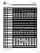
R/W 0xC090 Host 1 Status VBUS
Interrupt
Flag
ID
Interrupt
Flag
Reserved SOF/EOP
Interrupt
Flag
Reserved xxxx xxxx
Reserved Port A
Wake Interrupt
Flag
Reserved Port A Con-
nect
Change
Interrupt Flag
Reserved Port A
SE0
Status
Reserved Done
Interrupt
Flag
xxxx xxxx
R/W 0xC090 Device 1 Status VBUS
Interrupt
Flag
ID
Interrupt
Flag
Reserved SOF/EOP
Interrupt
Flag
Reset
Interrupt
Flag
xxxx xxxx
EP7
Interrupt
Flag
EP6
Interrupt
Flag
EP5
Interrupt
Flag
EP4
Interrupt
Flag
EP3
Interrupt
Flag
EP2
Interrupt
Flag
EP1
Interrupt
Flag
EP0
Interrupt
Flag
xxxx xxxx
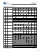
R/W 0xC092
0xC0B2
Host n SOF/EOP Count Reserved Count... 0010 1110
...Count 1110 0000
R 0xC092
0xC0B2
Device n Frame Number SOF/EOP
Timeout
Flag
SOF/EOP
Timeout
Interrupt Count
Reserved Frame... 0000 0000
...Frame 0000 0000
R 0xC094
0xC0B4
Host n SOF/EOP Counter Reserved Counter...
...Counter
W 0xC094
0xC0B4
Device n SOF/EOP Count Reserved Count...
...Count
R 0xC096
0xC0B6
Host n Frame Reserved Frame... 0000 0000
...Frame 0000 0000
R/W 0xC0AC Host 2 Interrupt Enable Reserved SOF/EOP
Interrupt
Enable
Reserved 0000 0000
Reserved Port A
Wake Interrupt
Enable
Reserved Port A Con-
nect Change
Interrupt
Enable
Reserved Done
Interrupt
Enable
0000 0000
R/W 0xC0AC Device 2 Interrupt Enable Reserved SOF/EOP
Timeout Inter-
rupt Enable
Wake
Interrupt
Enable
SOF/EOP
Interrupt
Enable
Reset
Interrupt
Enable
0000 0000
EP7
Interrupt
Enable
EP6
Interrupt
Enable
EP5
Interrupt
Enable
EP4
Interrupt
Enable
EP3
Interrupt
Enable
EP2
Interrupt
Enable
EP1
Interrupt
Enable
EP0
Interrupt
Enable
0000 0000
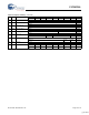
R/W 0xC0B0 Host 2 Status Reserved SOF/EOP
Interrupt Flag
Reserved xxxx xxxx
Reserved Port A
Wake Interrupt
Flag
Reserved Port A Con-
nect Change
Interrupt Flag
Reserved Port A
SE0
Status
Reserved Done
Interrupt
Flag
xxxx xxxx
R/W 0xC0B0 Device 2 Status Reserved SOF/EOP
Timeout
Interrupt
Enable
Wake
Interrupt
Flag
SOF/EOP
Interrupt
Flag
Reset
Interrupt
Flag
xxxx xxxx
EP7
Interrupt Flag
EP6
Interrupt Flag
EP5
Interrupt Flag
EP4
Interrupt Flag
EP3
Interrupt Flag
EP2
Interrupt Flag
EP1
Interrupt Flag
EP0
Interrupt Flag
xxxx xxxx
R/W 0xC0C6 HPI Mailbox Message... 0000 0000
...Message 0000 0000
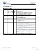
R/W 0xC0C8 SPI Configuration 3Wire
Enable
Phase
Select
SCK
Polarity Select
Scale Select Reserved 1000 0000
Master
Active Enable
Master
Enable
SS
Enable
SS Delay Select 0001 1111
R/W 0xC0CA SPI Control SCK
Strobe
FIFO
Init
Byte
Mode
FullDuplex SS
Manual
Read
Enable
Transmit
Ready
Receive
Data Ready
0000 0001
Transmit
Empty
Receive
Full
Transmit Bit Length Receive Bit Length 1000 0000
R/W 0xC0CC SPI Interrupt Enable Reserved... 0000 0000
...Reserved Receive
Interrupt
Enable
Transmit
Interrupt
Enable
Transfer
Interrupt
Enable
0000 0000
R 0xC0CE SPI Status Reserved... 0000 0000
FIFO Error
Flag
Reserved Receive
Interrupt Flag
Transmit
Interrupt Flag
Transfer
Interrupt Flag
0000 0000
W 0xC0D0 SPI Interrupt Clear Reserved... 0000 0000
...Reserved Transmit
Interrupt Clear
Transmit
Interrupt Clear
0000 0000
R/W 0xC0D2 SPI CRC Control CRC Mode CRC Enable CRC Clear Receive CRC One in CRC Zero in CRC Reserved... 0000 0000
...Reserved 0000 0000
R/W 0xC0D4 SPI CRC Value CRC.. 1111 1111
...CRC 1111 1111
Table 42. Register Summary (continued)
R/W Address Register Bit 15 Bit 14 Bit 13 Bit 12 Bit 11 Bit 10 Bit 9 Bit 8 Default High
Bit 7 Bit 6 Bit 5 Bit 4 Bit 3 Bit 2 Bit 1 Bit 0 Default Low
[+] Feedback