CSC-5500 Multi-Input Scaler Operation Manual
DISCLAIMERS The information in this manual has been carefully checked and is believed to be accurate. Cypress Technology assumes no responsibility for any infringements of patents or other rights of third parties which may result from its use. Cypress Technology assumes no responsibility for any inaccuracies that may be contained in this document. Cypress also makes no commitment to update or to keep current the information contained in this document.
SAFETY PRECAUTIONS Please read all instructions before attempting to unpack, install or operate this equipment and before connecting the power supply. Please keep the following in mind as you unpack and install this equipment: • Always follow basic safety precautions to reduce the risk of fire, electrical shock and injury to persons. • To prevent fire or shock hazard, do not expose the unit to rain, moisture or install this product near water. • Never spill liquid of any kind on or into this product.
CONTENTS 1. Introduction �������������������������������������������� 1 2. Applications ������������������������������������������� 1 3. Package Contents �������������������������������� 1 4. System Requirements ���������������������������� 1 5. Features �������������������������������������������������� 1 6. Operation Controls and Functions ������� 2 6.1 Front Panel ����������������������������������������2 6.2 Rear Panel �����������������������������������������3 6.
1. INTRODUCTION The Multi-Input Scaler has CV, Component, PC, and HDMI inputs and can scale the signal into HDMI, VGA with audio output ports. This high performance Multi-Input Scaler supports HDMI output resolution up to 1080p /WUXGA and Analog Digital Conversion (ADC) & Digital Analog Conversion (DAC) allowing a wide range of AV signal to be insert to a High-definition signal and displaying.
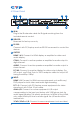
6. OPERATION CONTROLS AND FUNCTIONS 6.1 Front Panel POWER CV COMP PC 1 PC 2 PC 3 HDMI 1 HDMI 2 HDMI 3 720P MENU - + ENTER XGA 1 2 3 4 5 6 1 POWER button & LED: Press this button to switch ON or set the device to standby mode. Once the device is connected with power supply and the power toggle is switched to ON the LED will illuminate and the device will switch ON automatically. 2 IR: This IR window receives only the IR signal from the remote control included in the package.
6.2 Rear Panel 1 2 IR IN 3 6 SERVICE RS232 OUTPUT HDMI 1 HDMI 2 COAX PC/HD R L Cr/Pr Cb/Pb AUDIO AUDIO HDMI 1 HDMI 2 HDMI 3 4 PC 1 7 INPUT CONTROL PC 2 PC 3 Y R L POWER CV DC 5V 5 8 1 IR IN: Plug in the IR extender cable for IR signal receiving from the included remote control. 2 SERVICE: Reserved for factory use only. 3 RS-232: Connect with PC/Laptop and use RS-232 command to control the device.
DVD player for both video and audio signal sending. CV + L/R: Connect to source equipment such as video/DVD player for both video and audio signal sending. 6 CONTROL: This port is the link for Telnet or Web GUI controls, connect to an active Ethernet link with an RJ45 terminated cable (for further details, please refer to section 6.7 & 6.8. 7 POWER: Switch this power toggle to turn ON and activate the device or to turn OFF and shut it down.
8 ◄►: Press right and left buttons to increase and decrease the volume when outside of OSD menu selection. 6.
6.5 RS-232 and Telnet Commands ?: Show command list under Telnet.
S CONTRAST 0~60 Contrast Setting R CONTRAST Inquire contrast setting S BRIGHTNESS 0~60 Brightness setting R BRIGHTNESS Inquire brightness setting S HUE 0~60 Hue setting R HUE Inquire hue setting S SATURATION 0~60 Saturation setting R SATURATION Inquire saturation setting S SHARPNESS 0~30 Sharpness setting R SHARPNESS Inquire sharpness setting S NR 0~3 Noise reduction setting R NR Inquire noise reduction setting S VOLUME 0~100 Volume Setting R VOLUME Inquire Volume setting S AUDIODE
PORT (0~8) Set active port when repower on LAST MEMORY(0) / HDMI(1) / HDMI2(2) / HDMI3(3) / YPBPR(4) / VIDEO (5) / PC(6) / PC2(7) / PC3(8) ST FW vers. & source info. 0.00~x.xx SOURCE: HDMI ~ PC3 PORT ON:LAST ~ PC3 VOL + Volume up and down VOLUME * IS SET VOL QUIT EXIT (Telnet only) * 1 Resolution 0~13 are RGB encoded and resolution 14~21 are YUV encoded. All command will be not executed unless followed with a carriage return + LF and commands are case-insensitive.
6.
CONTRAST BRIGHTNESS COLOR COLOR HUE SATURATION SHARPNESS NR. VOLUME DELAY AUDIO SOUND SOURCE(HDMI mode only)*1 FACTORY RESET*2 KEY LOCK POWER SAVE IP MODE SETUP 0~60 (30) 0~60 (30) R 0~1023 (512) G 0~1023 (512) B 0~1023 (512) R OFFSET 0~1023 (512) G OFFSET 0~1023 (512) B OFFSET 0~1023 (512) 0~60 (30) 0~60 (30) 0~30 (0) OFF LOW MIDDLE HIGH 0~100 (100) OFF 40mS 110mS 150mS ON MUTE AUTO EXT. OFF ON OFF ON DHCP STATIC IP ADDRESS SET STATIC IP SUBNET MASK Def. Getway FREERUN COLOR 0.0.0.0.~255.255. 255.
INFORMATION INPUT OUTPUT REVISION IP ADDRESS Factory default setting. *1 When Audio Source is set on Auto, the device will send audio signal according to input source. If input signal is with HDMI, the device will use internal signal and if input signal is with DVI, the device will use external L/R audio. When Audio Source is set on EXT, the device will use external L/R audio. *2 Factory reset under OSD only reset part of settings to reset completely please use the reset button from the remote control.
6.7 Telnet Control Before attempting to use the telnet control, please ensure that both the Scaler (via the 'LAN port) and the PC/Laptop are connected to the active networks. To access the telnet control in Windows 7, click on the "Start" menu and type "cmd" in the Search field then press enter. Under Windows XP go to the "Start" menu and click on "Run", type "cmd" with then press enter. Under Mac OS X, go to Go→Applica tions→Utilities→Terminal See below for reference.
This will bring us into the device which we wish to control. Type "?" to list all the commands. Note: All command will not be executed unless followed by a carriage return. Commands are case-insensitive. If the IP is changed then the IP Address required for Telnet access will also needs to be change accordingly.
6.8 Web GUI Control On a PC/Laptop that is connected to an active network as the Scaler, open a web browser and type device's IP address on the web address entry bar. The browser will bring up the control page of Scaler.
7.
8. SPECIFICATIONS Input Ports 1 x Component with L/R, 1 x Composite with L/R, 3 x VGA, 3 x HDMI, 6 x Audio L/R (3.
8.
SXGA@60Hz V V UXGA@60Hz V V 1280x768@60Hz V V 1280x800@60Hz V V 1360x768@60Hz V V 1400x1050@60Hz V V 1440x900@60Hz V V 1680x1050@60Hz V V 1920x1200@60Hz(RB) V V 18
CYPRESS TECHNOLOGY CO., LTD Home page: http://www.cypress.com.